Synthesis of Nb0.8Hf0.2FeSb0.98Sn0.02 and Hf0.25Zr0.25Ti0.5NiSn0.98Sb0.02 Half-Heusler Materials and Fabrication of Thermoelectric Generators
Article information
Abstract
In this study, half-Heusler (HH) thermoelectric materials Nb0.8Hf0.2FeSb0.98Sn0.02 (p-type) and Hf0.25Zr0.25Ti0.5NiSn0.98Sb0.02 (n-type) were synthesized using induction melting and spark plasma sintering. For alloying, a conventional induction melting technique was employed rather than arc melting, for mass production compatibility, and the thermoelectric properties of the materials were analyzed. The maximum dimensionless figures of merit (zTmax) were 0.75 and 0.82 for the p- and n-type material at 650 °C and 600 °C, respectively. These materials were then used to fabricate generator modules, wherein two pairs of p- and n-legs without interfacial metal layers were brazed on direct bonded copper (DBC)/Al2O3 substrates using a Zr-based alloy. A maximum power of 0.57 W was obtained from the module by applying a temperature gradient of 476 °C, which corresponds to a maximum power density of 1.58 W cm -2 when normalized by the area of the material. The maximum electrical conversion efficiency of the module was 3.22% at 476 °C temperature gradient. This value was negatively affected by the non-negligible contact resistivity of the brazed interfaces, which ranged from 6.63 × 10 -9 Ωm2 to 7.54 × 10 -9 Ω m2 at hot-side temperatures of 190 °C and 517 °C, respectively. The low electrical resistivity of the HH materials makes it especially important to develop a brazing technique for ultralow resistance contacts.
1. Introduction
Thermoelectric technology has been utilized for cooling and power generation because of its salient features, including noiseless operation, small volume, and long-term reliability. Recent interests in eco-friendly power sources are invigorating research in waste heat recovery by thermoelectric generation (TEG). Among the many thermoelectric materials, halfHeusler (HH) materials have attracted attention for mid- to high- temperature applications up to 1,000 K. HH materials possess many merits, including high efficiency, mechanical robustness, low toxicity, and thermal stability [1-6]. MNiSn (M =Ti, Zr, or Hf) and RFeSb (R =V, Nb, or Ta) alloys are representative HH materials that have exhibited excellent thermoelectric performances, and a maximum dimensionless figure of merit (zTmax) of approximately 1.5 was recently reported for both materials [7,8].
Compared with the abundance of reports on HH material synthesis, reports on module fabrication and characterization are relatively scarce [1,5,6,9-13]. Developing robust and highly conductive metallization for mid-temperature modules is a challenging task that requires a reliable bonding process. The true difficulty stems from the intrinsically high electrical conductivity (σ) of HH materials; the electrical contact resistance (Rc) should be accordingly low to avoid degrading module performance. This is clearly shown in Equation (1) [14]:
where ZT and (zT)0 are the figures of merit for the module and material, respectively, and L is the length of the thermoelectric leg. Making the Rcσ term negligibly small is more difficult with HH materials.
Referring to previous reports, different strategies have been employed for bonding HH materials to fabricate modules. For example, Zillmann et al. deposited Au/TiW bilayers on Hf0.5Zr0.5CoSn0.2Sb0.8 and Hf0.6Zr0.4NiSn0.98Sb0.02 materials as diffusion barriers, which were subsequently sinter-bonded on Ag pads using Ag particles [13]. The contact resistivity was estimated to be 6.2 -10.0 × 10 -9 Ω m2 [13]. Yu et al. did not use interfacial layers between the HH legs and Cu electrodes. The hot-sides of their HH legs were brazed using a Ag -Cu -Zn alloy in vacuum, and achieved a contact resistivity of 2.0 × 10 -9 Ωm2 [5]. Likewise, Nozariasbmarz et al. employed direct brazing of Hf0.5Zr0.5CoSb0.8Sn0.2 and Hf0.75Zr0.25NiSn0.99Sb0.01 on Cu electrodes using a Cu -Ag - based material and reported a remarkable contact resistivity of less than 1 × 10 -10 Ω m2 [6]. Xing et al. obtained a low contact resistivity of 1.2 × 10 -9 Ω m2 using an Ag -Cu -Zn alloy for brazing of Zr0.5Hf0.5NiSn0.97Sb0.03 and Nb0.86Hf0.14FeSb. Their careful design of the HH modules resulted in the record power density of 3.1 W cm -2 and conversion efficiency of 10.5% [15]. In many cases, high-conductivity alloy metals containing Ag and Cu have been used for brazing.
In this study, Nb0.8Hf0.2FeSb0.98Sn0.02 (p-type) and Hf0.25Zr0.25Ti0.5NiSn0.98Sb0.02 (n-type) were synthesized, and used to fabricate HH modules. A Zr-based alloy metal containing Ni, Ti, and Cu as minor elements was selected for brazing to test the feasibility of a filler metal that does not contain Ag, a precious metal. Two-pair HH modules were fabricated by direct brazing without diffusion barriers, and the output performance was characterized.
2. Experimental Procedure
Elemental source materials of Hf (99.9%, 3-12 mm pieces, Alfa Aesar), Nb (99.95%, 3.175 mm diameter × 3.175 mm length slug, Alfa Aesar), Fe (99.99%, 3.2 -6.4 mm pieces, Alfa Aesar), Sb (99.999%, 2 mm grains, Kojundo), Zr (99.8%, 3–6 mm lump, Alfa Aesar), Ti (99.99%, 2–10 mm grains, Kojundo), Ni (99.995%, 3.175 -mm -diameter × 3.175 - mm –length slug, Alfa Aesar), and Sn (99.999%, 2–3 mm grains, Kojundo) were used for the synthesis of Nb0.8Hf0.2FeSb0.98Sn0.02 and Hf0.25Zr0.25Ti0.5NiSn0.98Sb0.02. Raw materials were weighed according to the stoichiometric composition, sealed in a quartz tube in an Ar atmosphere, and then melted completely by conventional RF induction heating equipment. The melted metal was immediately dipped into water for quenching, crushed manually into smaller pieces, and then vacuum-sealed in a quartz tube for a long anneal at 900 °C. The annealed materials were then ball-milled at 300 RPM (PM-100, Retsch) and sieved to filter out large particles (≥ 45 μm). The fine powders were loaded into a graphite mold (12.7 mm diameter) and spark plasmasintered (Dr. Sinter, Fuji Electronic Industrial) at 1100 °C (Hf0.25Zr0.25Ti0.5NiSn0.98Sb0.02) or 950 °C (Nb0.8Hf0.2FeSb0.98 Sn0.02) under pressure of 65 MPa. The sintered ingots were sawed into various sizes to measure resistivity (ρ), Seebeck coefficient (S), thermal diffusivity (a), and heat capacity (Cp).
The phases in the samples were identified using X-ray diffractometry (XRD, CuKα, X’Pert PRO MPD, Panalytical). The microstructural features were observed using field emission scanning electron microscopy (FE-SEM, S-4800, Hitachi), which was equipped with an energy dispersive X-ray spectroscopy (EDS) system for element mapping and quantitative composition analysis. ρ and S were simultaneously measured using a commercial system (ZEM-3, Ulvac-Riko). A differential scanning calorimeter (DSC 404C, Netzsch) and a laser flash measurement system (LFA-457, Netzsch) were used to measure the Cp and a of the samples, respectively. The density (d) of the samples was measured using the Archimedes method. From these parameters, thermal conductivity (κ) was calculated according to the relation κ = aCpd.
The two-pair HH modules were fabricated by brazing HH legs (leg dimensions: 3.0 mm × 3.0 mm × 5.0 mm) on direct bonded copper (DBC)/Al2O3 substrates (Cu thickness = 270 μm, area = 1 cm2) using commercial amorphous alloy foils containing Zr, Ni, Ti, and Cu (thickness = 65 μm) [16]. The heat cycle of brazing was completed in a rapid thermal processing chamber with halogen lamps, where the HH modules were heated at 830 °C in a N2 atmosphere for two minutes. Both the hot- and cold- sides of the HH legs were brazed with the same Zr-based alloy. The fabricated modules were characterized using a commercial system (Mini-PEM, Advance Riko, Inc.) that measures the output power and thermoelectric conversion efficiency for small modules up to the highest hot-side temperature of approximately 500 °C. During the measurement in this study, the hot side of the module was heated up to the highest temperature of 517 °C, during which the temperature of the water-cooled cold side was slightly raised to 41.5 °C through heat conduction.
3. Results and Discussion
3.1 Materials synthesis and thermoelectric performances
Fig 1 presents the XRD patterns of the sintered Nb0.8 Hf0.2FeSb0.98Sn0.02 and Hf0.25Zr0.25Ti0.5NiSn0.98Sb0.02. All major peaks are clearly identified according to the reference patterns of NbFeSb (ICSD ID: 83928) and ZrNiSn (ICSD ID: 80486), and no other peaks from impurity phases are observable.

XRD patterns from the as-sintered Nb0.8Hf0.2FeSb0.98Sn0.02 and Hf0.25Zr0.25Ti0.5NiSn0.98Sb0.02 samples.
Fig 2 illustrates the thermoelectric properties of the HH materials. In Fig 2(a), the resistivity values of both materials are in the 10 -6 Ω m range and increase monotonically with temperature, showing metallic conduction behavior. The absolute values of the Seebeck coefficients also increase with temperature and reach comparable maximum values of 1.68 × 10 -4 V K -1 and -1.66 × 10 -4 V K -1 at 700 °C, as illustrated in Fig 2(b). From the resistivity and Seebeck coefficient, the power factor (PF) is calculated from the relation PF = S2/ρ, and the results are illustrated in Fig 2(c). Overall, the PF of Nb0.8Hf0.2FeSb0.98Sn0.02 is higher than 4.0 × 10 -3 W K -2m -1 over the whole temperature range, and PFmax is 5.2 × 10 -3 W K -2m -1 at 300 °C, whereas Hf0.25Zr0.25Ti0.5NiSn0.98Sb0.02 has lower PFmax of 4.4 × 10 -3 W K -2m -1 at 400 °C. Consequently, the low resistivity of Nb0.8Hf0.2FeSb0.98Sn0.02 produced high PFs.

Thermoelectric properties of the Nb0.8Hf0.2FeSb0.98Sn0.02 and Hf0.25Zr0.25Ti0.5NiSn0.98Sb0.02: (a) electrical resistivity; (b) Seebeck coefficient; (c) power factor; (d) thermal conductivity; and (e) the dimensionless figure of merit.
Fig 2(d) illustrates the thermal conductivity (κ) of both materials. It is observed that Nb0.8Hf0.2FeSb0.98Sn0.02 has higher values over the whole temperature range. The κ of Nb0.8Hf0.2FeSb0.98Sn0.02 monotonically decreases from 9.1 W K -1m -1 at 25°C to 5.4 W K -1m -1 at 700 °C, whereas that of Hf0.25Zr0.25Ti0.5NiSn0.98Sb0.02 is relatively constant around approximately 5 W K -1m -1. From the above parameters, the zT values were calculated using the relation zT = PF·T/κ, as illustrated in Fig 2(e), and the zTmax of the p- and n-type HH materials was 0.75 and 0.82 at 650 °C and 600 °C, respectively.
3.2 Module fabrication and characterization
Fig 3 presents cross-sectional SEM images of the brazed interfaces and corresponding elemental distribution profiles along the yellow vertical lines indicated in Figs 3(a) and 3(c). The brazed interfaces of both materials are smooth with no structural imperfections, and the thicknesses of the interfacial layers are approximately 25 and 20 μm for n- and p-type HH, respectively. Fig 3(b) indicates that the interface between Hf0.25Zr0.25Ti0.5NiSn0.98Sb0.02 and the brazing layer is abrupt with an interfacial mixed region with a thickness of approximately 3 μm. The brazing layer is also shown to be mainly composed of Zr, Ti, and Cu. In the case of Nb0.8Hf0.2FeSb0.98Sn0.02, Zr and Ti are piled up at the interface with the brazing layer, as confirmed in Fig 3(d). The main components of the brazing layer were Cu, Zr, and Nb, whose concentrations are quite uniform along the layer. Overall, direct brazing without a diffusion barrier layer resulted in stable bonding and limited reaction at the interfaces. Penetration of Cu into the HH legs was not observed despite the high brazing temperature of 830 °C.
(a) Cross-sectional SEM image of the brazed interface of Hf0.25Zr0.25Ti0.5NiSn0.98Sb0.02 and a Cu pad using a Zr-based filler metal; (b) elemental distribution profiles along the yellow line shown in (a); (c) cross-sectional SEM image of the brazed interface of Nb0.8Hf0.2FeSb0.98Sn0.02 and a Cu pad; and (d) elemental distribution profiles along the yellow line shown in (c).
Fig 4 illustrates the two-pair HH generator module, and its thermoelectric performance. As illustrated in Fig 4(b), the output voltage and power increase as the temperature gradient (ΔT) across the module is increased. A maximum power of 0.57 W was obtained at ΔT = 476 °C and a current of 6.4 A. Fig 4(c) shows the maximum power density (Pmax) at each ΔT, which is normalized by the area of the module and the material (legs), respectively. When normalized by the material area, the maximum power density of the module was 1.58 W cm -2 at ΔT = 476 °C. The open-circuit voltage (Voc) increased linearly, up to 0.19 V, with ΔT, as illustrated in Fig 4(d). The maximum conversion efficiency of the twopair module was estimated to be 3.22% at ΔT = 476 °C.
(a) Photograph of the two-pair HH module; (b) voltage and power versus current of the module under varying ΔT; (c) power density versus ΔT with respect to the legs and the module area; (d) the open-circuit voltage (Voc) and efficiency versus ΔT.
Compared with the results of previous reports by other groups (Table 1), the overall performance of our HH modules is relatively lower. The primary reason for this is the lower ΔT in this study. We also believe that the material properties should be further improved. In addition, contact resistance plays a critical role in deteriorating the ideal performance of the modules, as shown in Equation (1). Accordingly, the contact resistivity of the brazed interfaces was estimated based on the output characteristics of the HH module.
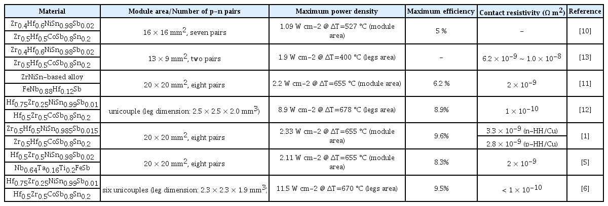
Performance of HH generator modules reported in recent representative studies
First, the internal resistance of the module (Rint) was estimated from the voltage -current relation in Fig 4(b), which is plotted in Fig 5(a) as a function of the hot-side temperature, TH. The Rint of our module was approximately 12.7 mΩ at TH = 190 °C and increased linearly up to 15.8 mΩ at 517 °C. Since Rint is composed of the resistances of the thermoelectric materials (RTE), contacts (Rcontact), and Cu pads (Rpad), if we ignore the negligible contribution from Rpad, Rcontact can be estimated using the following relation:

(a) Module resistance (measured) and leg resistance (calculated) versus hot-side temperature TH; (b) calculated contact resistivity versus hot-side temperature TH.
The RTE is easily calculated from the resistivity data of the HH materials in Fig 2(a) by assuming that the temperature gradient is constant along the HH legs; the final result is plotted in Fig 5(a). It is noted that the Rint is approximately twice as high as RTE, showing that the magnitude of Rcontact is comparable to that of RTE.
Normalizing Rcontact by the area of the contacts and the number of interfaces leads to a contact resistivity of 6.63 × 10 -9 Ω m2 at TH = 190 °C, which increases up to of 7.54 × 10 -9 Ω m2 at 517 °C as illustrated in Fig 5(b). This estimation is based on a simple assumption that the contact resistivity values for p- and n-type HH materials are equal. When one compares the magnitudes of contact resistivity, the Zr-based filler metal in this study produces somewhat higher values than the cases using Ag -Cu -Zn, which were in the range 1.2 -2.0 × 10 -9 Ω m2 [5,15]. This discrepancy may partly arise from the intrinsically higher resistivity of Zr (4.21 × 10 -7 Ω m at 20 °C) than Ag (1.59 × 10 -8 Ω m at 20 °C) and Cu (1.68 × 10 -8 Ω m at 20 °C). Nevertheless, further optimization of the brazing process, including soaking temperature and time, is expected to lower the contact resistivity. Reducing the contact resistivity below 1 × 10 -9 Ω m2 would be required to maximize the conversion efficiency and output power of our HH modules.
4. Conclusions
In this study, HH materials were fabricated and brazed to make two-pair thermoelectric generator modules. Nb0.8Hf0.2 FeSb0.98Sn0.02 and Hf0.25Zr0.25Ti0.5NiSn0.98Sb0.02 were synthesized by induction melting and spark plasma sintering, and the zTmax values of 0.75 and 0.82 were obtained for the p- and n-type material, respectively. For metallization of the HH legs, direct brazing without diffusion barrier layers was implemented using a Zr-based amorphous alloy. Smooth and abrupt interfaces were produced with a contact resistivity of about 6.63 × 10 -9 Ω m2 at TH = 190 °C. The maximum power output of the two-pair HH modules was 0.57 W at ΔT = 476 °C, which corresponds to a maximum conversion efficiency of 3.22%. Establishing an optimized brazing process is crucial to increase the module performance.
Acknowledgements
This research was supported by Korea Electrotechnology Research Institute(KERI) Primary Research program through the National Research Council of Science & Technology (NST) funded by the Ministry of Science and ICT (MSIT) (no. 21A01011).
Notes
All authors declare no conflicts of interest.