Electrochemical Characteristics of Elastic, Non-Polar Polyurethane-Based Polymer Gel Electrolyte for Separator-Less Lithium-Ion Batteries
Article information
Abstract
Lithium-ion batteries (LIBs) have undergone countless enhancements in the past decade, mainly improvements in the basic components: electrodes, electrolyte, and separator. The separator, which acts as a physical barrier between the two electrodes, does not directly participate in the charge and energy storage. However, it is involved in the safety, form factor, and packaging density of the LIBs. While it occupies relatively less internal space than other components, the separator can be replaced with active materials such as gel polymer electrolytes (GPEs) which can serve as both the electrolyte and physical barrier between the electrodes. GPEs can potentially minimize the risks of liquid electrolytes, including flammability, electrolyte leakage, and explosion. Here we report the characteristics of polyurethane (PU)-based gel swollen in concentrated electrolyte solutions in separator-less cells. The poreless PU-based gel electrolyte conducts lithium ions, while preventing internal short-circuits. This is attributed to the presence of soft segments, which allow ion transport, and hard segments, which ensure mechanical integrity. Electrochemical measurements carried out in LFP half cells and symmetric Li cells revealed that the separator-less cells were operable between 0.2 C to 1 C rates, and that during long term cycling, the cells achieved stable Li electroplating overpotential, as the number of cycles increased.
1. INTRODUCTION
Lithium-ion batteries (LIBs) have been revolutionary in the energy research field worldwide, with a wide range of applications including computers, mobile devices, and electric vehicles among others [1-5]. Because of their high specific energy and superior cyclability, the demand for LIBs continues to rise rapidly [6]. The main efforts for improving performance have focused on enhancing the fundamental component technologies, such as exploring new electrode materials [7,8], tough separators [9,10], concentrated electrolytes [11-13], and conductive binders [14].
The basic components of a single LIB include a cathode, an anode, electrolyte, and a separator. The separator is placed between the cathode and anode and acts as a physical barrier to prevent physical contact between the two electrodes, while still allowing Li+ ion conduction through it [6]. Although not directly participating in the energy and charge storage, the separator influences the overall properties of LIBs, such as performance, lifetime, safety, and cell production [13]. While it occupies a relatively smaller internal space than other components, it can be replaced with active materials such as solids or gels that can act as both the electrolyte and physical barrier between the electrodes.
Previous reports have shown that traditional carbonate-based liquid electrolytes can be replaced with gel-like materials, such as hydrogels or organogels incorporating polymers [15-18]. This strategy minimizes the risks of liquid electrolytes, including flammability, electrolyte leakage, and explosion [19]. A separator-less rechargeable Cu – Zn battery has been proposed by Mypati et al. which utilizes a hydrogel-based electrolyte [20]. The maximum specific capacity of 280 mAh/g was recorded at a current density of 1 mA/cm2 and long-term charge-discharge cycling revealed that the hydrogel successfully inhibited the growth of dendrites, which can be rampant in the Zn metal anode.
One of the most widely used types of gel electrolytes are polymer gel electrolytes (GPE). The potential of PEO-based [21,22], PMMA-based [23,24], PAN-based [25,26], and PVdF-based [27-31] GPEs have been well-established in previous reports. However, several drawbacks with the use of these polymers have also been noted. While exhibiting high solvating power and excellent compatibility with Li electrodes, PEO is mechanically weakened by organic solvents, which function as plasticizers [32]. In the same way, the mechanical properties of PMMA also decrease when ionic conductivity is enhanced [33,34]. On the other hand, PAN, which exhibits outstanding mechanical and electrochemical properties, suffers from a severe side reaction (passivation) when in contact with Li metal electrodes [35]. PVdF is typically used in GPEs due to its high liquid electrolyte uptake, and superior solvation of Li salts [36-38]. However, the use of toxic solvents, such as N-Methyl-2-pyrrolidone (NMP) during preparation, and relatively high crystallinity—which usually hinders Li ion mobility—pose drawbacks to the use of this polymer [39].
Polyurethane (PU) is a polymer characterized by repeated urethane groups (—NHCOO-). It has gained attention for its potential in GPE applications due to its mechanical strength and toughness, flexibility, and compatibility with other polymers. The presence of soft segments, which enable Li+ transport, and hard segments, which ensure mechanical strength, makes PU increasingly attractive as a new polymer matrix for GPEs [40,41].
In this work, we report the electrochemical characteristics of elastic, non-polar polyurethane-based polymer gel electrolyte for separator-less lithium-ion batteries. The gel electrolyte is prepared via in-situ gelation by concentrated LiTFSI-based electrolyte. In-situ gelation occurs due to absorption of the concentrated LiTFSI-based electrolyte into the TPU matrix. Electrochemical characterization, carried out in LFP half-cells and symmetric Li cells, revealed operable C-rates were between 0.2 C to 1 C, and long term cycling showed Li electroplating overpotential was stable.
2. EXPERIMENTAL
2.1 Materials
The following chemicals and materials were used as purchased without further purification: lithium bis(trifluoromethanesulfonyl)imide (LiTFSI; >99.0 %, Sigma Aldrich), propylene carbonate (PC; 99.5 %, Sigma Aldrich), tetrahydrofuran (THF; 99.8 %, Samchun Chemicals), lithium iron phosphate (LFP, battery grade LiFePO4, MTI corporation), polyvinylidene fluoride (PVdF; 99.5 %, MTI Corporation), conductive carbon black (graphite and carbon SuperP, TIMCAL), N-methyl-pyrrolidinone (NMP; 99.5 %, Duksan Reagents), Li metal foil (Li foil; MTI corporation, EQ-Lib-LiC25-1400), glass fiber separator (Cyvita, Whatman GF/F).
2.2 Preparation of concentrated LiTFSI electrolytes
Concentrated electrolytes were prepared using LiTFSI and anhydrous PC. Different concentrations (2.5 M and 3.0 M) were prepared by slowly dissolving varying amounts of LiTFSI in PC via mechanical stirring inside an Ar-filled glovebox at room temperature. Stirring continued for 1 h to allow complete dissolution.
2.3 Fabrication of polyurethane (PU) films
Thermoplastic polyurethane (TPU) was first dissolved in tetrahydrofuran (THF) in 0.068 wt/v % by mechanical stirring at room temperature for at least 1 h. Using a doctor blade applicator, the solution was cast on a glass substrate then dried in an oven at 70 °C overnight. Finally, the dried film was punched into 19 mm-diameter disks.
The surface morphology of the freestanding PU-based films dried at different temperatures was observed using scanning electron microscopy (SEM, HITACHI S-4300). X-ray diffraction (XRD, D8 Advance X-ray diffractometer, Bruker, Germany), with Cu Kα1 radiation (λ = 0.154059 nm) and scan rate of 3 °/min, was used to investigate the structure of the as-prepared and swollen films.
2.4 Cell assembly
Two-electrode configuration coin cells (CR2032; Wellcos Corporation) were assembled inside an Ar-filled glovebox at room temperature, with 2 different cell configurations: an LFP half-cell and a symmetric Li cell.
To fabricate the LFP half-cells, a slurry was first prepared using LFP powder, PVdF, and Super P in NMP in 8:1:1 weight ratio, blended in a mixer (ARM-310, THINKY) for 20 mins. The blended slurry was coated on Al foil using a doctor blade then dried at 70 °C in a vacuum oven for 2 h before roll pressing (calendaring). It was further dried at 120 °C in a vacuum oven overnight. The final form of the electrodes was prepared by cutting the coated foils into circular disks of 10 mm diameter. The Li electrodes were prepared by punching Li foils into circular disks (diameter = 11 mm or 19 mm).
The coin cells were assembled using Li foil as the counter and reference electrodes, LiTFSI in PC as the electrolyte, and a separator—except for the separator-less cells which used the PU film—as shown in Figure 1. The assembled cells rested at room temperature for 24 h to allow wetting of the electrodes. Cells with LFP and Li electrodes are designated ‘LFP half-cells’ while those with only Li electrodes are referred to as ‘symmetric Li cells’.

Schematic diagram of CR2032 coin cells: (left) using commercial separator and (right) separator-less PU-based gel polymer electrolyte.
2.5 Electrochemical measurements
Electrochemical measurements were carried out in a battery cycler system (WBCS3000L, WonATech) at a constant temperature of 25 °C, unless otherwise stated. Cyclic voltammetry (CV) was used to characterize the redox potentials of the concentrated electrolytes in the LFP half-cells at a potential window of 3.0 V to 4.5 V and a scan rate of 0.1 mV/s for 12 cycles. The cycle life of the symmetric Li cells was evaluated by galvanostatic charge and discharge for 500 cycles at a constant current density of 1 mA/cm2. The rate capability of the separator-less cells was investigated by cycling the cells at various C-rates: 0.2 C, 0.5 C, 1 C, 2 C, 5 C and 10 C.
Electrochemical impedance spectroscopy (EIS) was carried out using an impedance spectrometer (WonATech, ZIVE SP1) by applying a 10 mV AC perturbation in the frequency range of 1 MHz − 100 mHz.
3. RESULTS AND DISCUSSION
3.1 Concentrated electrolytes: LiTFSI in PC
The electrochemical properties of the prepared electrolytes at concentrations 2.5 M and 3.0 M were characterized by CV using LFP half-cells (Figure 2a). The CV curves showed characteristic peaks at ~3.6 V and ~3.4 V vs Li/Li+ corresponding to lithiation and delithiation, respectively. It can be noted that for both electrolyte concentrations, peak shifting was observed from the 1st to the 10th cycle. This was further characterized by determining the separation of the cathodic and anodic peaks (Figure 2a inset). The 2.5 M electrolyte exhibited a decreased peak separation, suggesting that the overpotential decreased after 10 cycles. For the 3.0 M electrolyte, the peak separation increased from the 1st cycle to the 10th cycle. It was also observed that the magnitude of the current increased, as characterized by the peak heights of both electrolytes.

Electrochemical characteristics of the 2.5 M and 3.0 M LiTFSI-PC electrolytes in LFP half-cells: (a) CV curves cycled under 3.0 V – 4.5 V vs. Li/Li+ at 0.1 mV/s scan rate; (inset) separation of characteristic peaks at 1st and 10th cycles; and (b) Nyquist plots for EIS data collected after CV.
The Nyquist plots in Figure 2b compare the resistance of the cells using the different electrolytes after 12 CV cycles. It can be noted that the internal resistance of the cell using the 2.5 M electrolyte is lower than that of the 3.0 M electrolyte, due to ionic conduction. This can be attributed to the lower ionic conductivity of the highly concentrated electrolytes, and hence their increased viscosity [42]. At higher salt concentrations in organic solvents, solute ions easily aggregate to form crystalline solvate phases or ion pairs, both of which decrease ionic conductivity [12].
Figure 3a shows the long term galvanostatic charge-discharge cycling voltage profiles of four electrolytes: 1.0 M, 2.5 M, and 3.0 M LiTFSI in PC, and a reference commercial 1.0 M LiPF6 in EC:DMC:EMC. Symmetric Li cells were used at a constant current density of 1 mA/cm2 for 500 cycles. In general, high overpotentials were observed in the initial cycle(s) compared to the succeeding cycles. This can be attributed to the nucleation overpotential of Li, which generally requires a higher voltage for the initial nucleation, compared to the further growth processes [43].
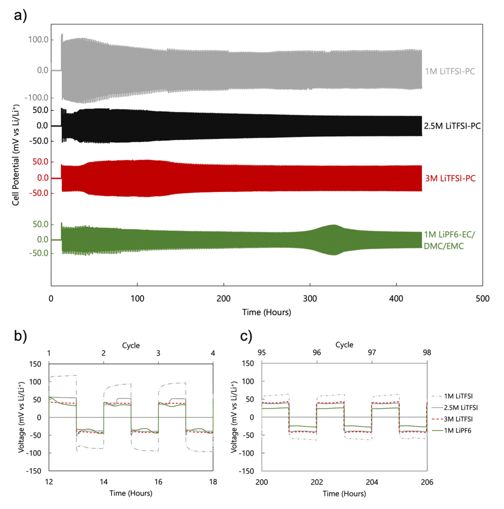
Voltage profiles of symmetric Li cells in 1.0 M LiTFSI-PC, 2.5 M LiTFSI-PC, 3.0 M LiTFSI-PC, and 1.0 M LiPF6-EC/DMC/EMC: (a) long-term cycling at 1 mA/cm2 for 500 cycles; (b) first 3 cycles and (c) 95th to 97th cycles of the voltage profile.
The first 3 cycles (Figure 3b) show that the overpotential, which is affected by both the interfacial and bulk resistance, is highest for 1.0 M LiTFSI followed by the 2.5 M LiTFSI and 3.0 M LiTFSI, and the 1.0 M LiPF6 in EC:DMC:EMC. Peaks and plateaus can also be observed at the beginning and end of the cycles. These are mainly caused by phenomena including nucleation, dendrite stripping, Li recovery, and pitting [11]. An increase in the overpotential was observed for the LiPF6 electrolyte after around 300 h of cycling. This is likely due to the reversible formation/plating of Li dendrites.
At the 95th cycle (Figure 3c), the overpotentials were reduced—this was more observable for the 1.0 M LiTFSI— and the peaks and plateaus are not seen. This indicates that the overpotentials of the 2.5 M and 3.0 M LiTFSI electrolytes were similar to each other, while higher ionic conduction was exhibited in the 2.5 M (Figure 2b). Accordingly, the 2.5 M LiTFSI electrolyte was selected for GPE construction for the remainder of this research.
3.2 Separator-less cells
3.2.1 Freestanding polyurethane (PU) films
The mechanical stretchability of freestanding PU film was observed (Figure 4). TPU is known to extensively swell, or be practically soluble in THF, which is why it was selected as the solvent to form the freestanding PU films. In addition, THF has a relatively low boiling point compared to other organic solvents, which makes it an attractive solvent since it does not require high temperature processing. The measurements showed the as-dried film had 100 % stretchability.
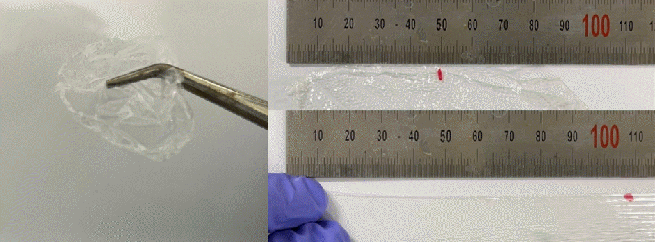
Freestanding PU film showing at least 100 % stretchability.
Figure 5a shows SEM micrographs of the freestanding PU films dried at various temperatures: 70 °C, 80 °C, 90 °C, and 100 °C. The sample dried at 70 °C shows a smooth surface with localized swelling of the film. This is due to the pressure build-up of gas under the film from the evaporation of THF solvent, which has a boiling point of 66 °C. At increased temperatures, porous structures are formed, which were more prominent at 90 °C and 100 °C. This resulting surface morphology is due to the faster rate of evaporation of the THF and the increased gas pressure build-up at higher temperatures. The gas bubbles trapped under the film are released by puncturing the surface, forming holes in the film. SEM micrographs of the actual PU-based gel polymer electrolyte used in the assembled cell were not acquired due to the presence of PC, which is volatile in vacuum.
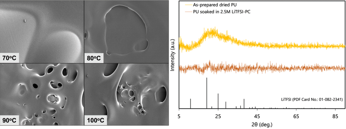
(a) SEM micrographs of freestanding PU films dried at various temperatures; (b) X-ray diffraction patterns of as-prepared PU film, PU soaked in 2.5 M LiTFSI-PC electrolyte, and LiTFSI.
The surface morphology of the PU film is important to the fabrication of a separator-less cell. The existence of porous structures in the film may serve as designated pathways for dendrite growth between the electrodes. Such porous structures are less capable of suppressing the formation of lithium dendrites during cycling, which are known to cause internal short circuits in the cell, finally leading to cell death [44]. Meanwhile, a smooth structure will more likely suppress dendrites since there is no pathway for the their growth—that is, there is a physical barrier formed between the electrodes.
The XRD patterns (Figure 5b) show the amorphous phase of the prepared PU film, characterized by the broad amorphous halo centered around 2q = ~23°. While the TPU consists of both hard and soft segments, it lacks a specific dspacing which results in the absence of a diffraction peak. Comparing the XRD pattern of the PU film soaked in 2.5 M LiTFSI-PC electrolyte with the standard diffraction pattern of LiTFSI (JCPDS No. 01-082-2341) revealed that there were no undissolved and phase-segregated crystalline LiTFSI salts. This suggests that at 2.5 M concentration, the LiTFSI remains in a dissolved state in the TPU-based organogel electrolyte and precipitation can be excluded.
3.2.2 Electrochemical characterization of separatorless cells
The electrochemical characterization of the separator-less cells was carried out by replacing the glass fiber separator in the assembled cells with the prepared PU films, allowing them to soak and eventually, swell in 2.5 M LiTFSI. The voltage profiles using LFP half-cells (Figure 6a) show a drift in the open circuit voltage (OCV) of the cell during the 24 h of rest time. Upon cycling at a constant current (galvanostatic charge – discharge), a high overpotential is revealed. This may be attributed to the increase in the internal resistance of the cell, as seen in the Nyquist plot (Figure 6b), compared to the cell with a commercial separator (Figure 2b).

Electrochemical characteristics of the separator-less LFP half-cell in 2.5 M LiTFSI-PC-swollen TPU gel electrolyte (a) voltage profile at 0.2 C, (b) Nyquist plot (as-assembled), (c) rate capability, and (d) charge capacity profile.
Rate capability was tested by continuously cycling the cell at various C-rates, ranging from 0.2 C to 10 C, as summarized in Figure 6c, while the capacity profile at representative cycles is shown in Figure 6d. Charge capacities ranging from around 30 mAh/g to 45 mAh/g were recorded at 0.2 C to 1 C. A sudden drop in capacity was observed at 2 C which further decreased at 5 C and 10 C. While the capacity ultimately recovered at 0.2 C, it decreased to almost 0 mAh/g at 2 C until the 50th cycle.
The conductivity of the assembled separator-less symmetric lithium cell containing the PU-based gel electrolyte was measured using EIS. The Nyquist plot showed two semi-circles, with the one at the lower frequency range having a larger diameter. The existence of two semicircles implies the presence of at least 2 resistances: the interfacial resistance (higher frequency regime) and charge transfer resistance (lower frequency regime). The larger diameter of the second semi-circle indicates that the charge transfer resistance is larger than the interfacial resistance.
The life cycle of the same cell was then examined, and the voltage profile was obtained (Figure 7b). It was observed that from an initially high value, the overpotential decreased as the number of cycles increased. This suggests that the cell became more stable as the number of cycles increased, as evidenced by the more consistent overpotential value above 100 h of running time. It was further inferred that the cell undergoes an activation phase before it becomes stable for long term cycling.
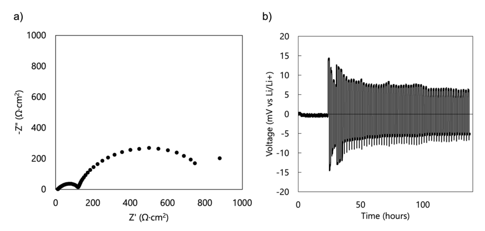
(a) Nyquist plot (as-assembled) and (b) voltage profile at a constant current of 1 mA/cm2 of fabricated separator-less symmetric Li cells in 2.5 M LiTFSI-PC-swollen TPU gel electrolyte.
4. CONCLUSIONS
We report the electrochemical characteristics of an elastic, non-polar polyurethane-based polymer gel electrolyte for separator-less lithium-ion batteries. Concentrated LiTFSI in PC electrolytes were prepared and characterized, as it is suitable to swell the TPU. Electrochemical characterization showed that the 2.5 M LiTFSI in PC electrolyte had a lower resistance than the 3.0 M electrolyte. It was also observed that cycling stabilized and reduced the overpotential of the 2.5 M electrolyte, as evidenced by the decrease in peak separation during CV.
The fabricated separator-less cell incorporating the 2.5 M LiTFSI-PC-swollen TPU gel electrolyte was characterized in an LFP half-cell configuration. EIS revealed increased resistance upon substitution of the GPE, which was further confirmed by the high overpotential observed in the voltage profile of the same cell at 0.2 C. Rate capability test showed cell stability at 0.2 C to 1 C with a maximum capacity value of 43 mAh/g measured at a 1 C rate. Long term cycling using a symmetrical Li cell showed decrease in overpotential as the number of cycles increased, and stability was observed at around 100 h of cycling. Conductivity measurements using EIS suggested the presence of 2 resistances—interfacial and charge transfer resistance—with the latter having an apparently higher value, as indicated by the larger diameter of the semicircle formed in the lower frequency regime of the Nyquist plot.
Acknowledgements
This research was supported by Electronic Component R&D Program through the Korea Evaluation Institute of Industrial Technology (KEIT) funded by the Korea government (MOTIE) (Award Number 20016367). Dongwook Lee was supported by 2023 Hongik University Research Fund.