


1. Introduction
Recently, global automobile companies have struggled with the trends of international environmental regulations, particularly fuel economy and greenhouse gas emission standards. To address these trends in the global market, automobile industries are manufacturing increasingly lighter vehicles to achieve higher energy efficiency. For this purpose, aluminum chassis and die cast parts are promising alternative components that can replace steel alloys while reducing the total weight of vehicles. Aluminum die cast parts are made by the die casting process, and utilize die-casting molds made from tool steels, such as AISI 4140 or H13. The conventional mold making process is composed of the following: i) sourcing the mold base steel for the cavities and other accessories from a massive billet, ii) CNC rough machining, iii) heat treatment, iv) fine machining (by milling, drilling, and wire cutting), v) polishing, and vi) the mold assembling.
In the rough machining stage, a large amount of scrap is formed when machining of cavities from the huge steel billets, and this results in the unnecessary material costs. Furthermore, the lead-time for mold making would be too long to attempt machining from a massive billet, in addition to the time needed for fine machining and polishing for modification.
Alternatively, a die-casting mold can be made using the additive manufacturing (AM) process, which only requires the base plate and material for additive manufacture. In direct energy deposition (DED), one of the AM processes, a powder or solid filler material is deposited using a directly exposed locally focused energy source such as an electron beam, arc, or plasma [1]. Wire-arc additive manufacturing (WAAM) is a DED type AM process that deposits a solid metal filler wire using a conventional gas metal arc welding (GMAW) process as the energy source. This process has an extremely high deposition rate, larger lot-size, and high modifiability compared to the powder-based AM process, as well as the availability of commercial equipment and filler material [2]. In addition, it can minimize material loss by stacking the weld bead, based on the component design, and shorten the lead-time because it has a faster manufacturing speed than the conventional mold-making process mentioned above. The process can potentially be used to fabricate the die-casting mold with the WAAM using 5 Cr – 4 Mo tool steel wire as a filler material, because of its high heat wear resistance and toughness.
Despite the aforementioned advantages and potential, few studies have been conducted on the WAAM of tool steels or die casting mold steels. Recently, research has been reported on the GMAW-based WAAM on various metal alloys of steel, aluminum, and bronze. However, the tool steels for mold making have not yet been reported.
The shielding gas greatly affects the WAAM product quality, compared to the GMAW process. The main role of shielding gases is protect the weld pool from the atmospheric reactive gases, so that preventing undesirable reacts or contamination on the weld pool [3]. Furthermore, it influences the overall weld quality, such as bead and penetration profile, surface condition, and formation of slag and defects, as well as the level of fume and spatter [4]. In general, argon (Ar), carbon dioxide (CO2) and oxygen are used for the GMAW of steel alloys, either as a single gas or mixture (hydrogen, nitrogen, and helium also blended in some cases), depending on the chemical composition of the target material [3-7]. Each gas has different gas properties (thermal conductivity, specific heat, heat intensity and reactivity), and thus have different effects on the abovementioned output results from the welding [8]. Thus, care should be taken when selecting the shielding gas for WAAM.
This project aims to find out the possibility of mold making by the WAAM process. This paper discusses the effects of the shielding gases on the additive manufacturability of commercial 5 Cr – 4 Mo tool steel solid wire on thick SCM 440 (AISI 4140) using the GMAW process.
2. Materials
A plate of SCM 440 alloy was used as a substrate for the experiments. A solid filler wire of commercial tool steel was used, which was composed of 5 Cr – 4Mo with a low carbon content. Table 1 lists the chemical composition of each material.
3. Experimental Method
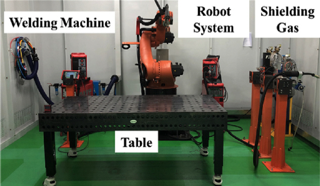
The experiment was conducted by using a cold metal transfer (CMT) welding machine and robotic system with an experimental table, as shown in Fig 1. Table 2 lists the experimental parameters used. A heat input of approximately 600~650 J/mm and a contact tip to work distance (CTWD) of 15 mm was given. M21 (Ar + 18% CO2) and C1 (100% CO2) shielding gases were selected, referring to the filler wire manufacturer’s guide, EN ISO 14175 [5] and DIN 32 526 [9]. The bead-on-plate (BOP) test, 3 × 3 stacking experiment as a small scale AM, and large scale AM were conducted with two different shielding gases. For each, the travel length was 120 mm, while the height was varied with the scale of the sample. The overlap distance was 6.5 mm which represents the interval distance of each pass in one layer for the AM. And the interlayer distance set as 3.0~3.5 mm, which was somewhat varied with the bead height to meet the 15 mm of CTWD.
To identify the proper shielding gas, the manufactured samples were evaluated using i) defect, ii) geometry of the deposited metal, iii) deposition amount, and iii) mechanical property. Defect analysis was performed by visual inspection and a 3D-CT. The samples were wire cut, chemical-mechanical polished, and chemically etched to analyze the geometry of the deposited metal and deposition amount. The macro- and micro-chemical etching was conducted using a Nital and Vilella etchants, respectively. The micro Vickers hardness test was conducted at loads of 0.2 kgf to observe the micromechanical property. The tensile shear test was conducted, as well as the fractography analysis using scanning electron microscope (SEM). The samples were grouped based on the type of shielding gas used for AM, and were designated UM (using M21 gas) and UC (using C1), respectively.
4. Result and Discussion
4.1 BOP test
4.1.1 Visual inspection
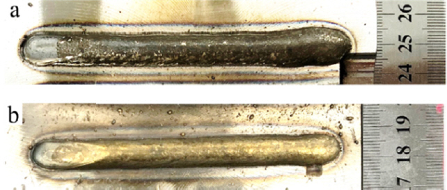
BOP tests were conducted using the parameters described in Table 2. Fig 2 shows the top-view macro images. The amount of spatter, surface weld scale, and smut were similar in both cases. On the other hand, sessile weld scale formed on the surface of the UM that could not be removed by brushing. This resulted in surface contamination, which can be the cause of weld defects, such as porosity, and can induce an unstable arc in the multi-pass welding process [10-12]. In contrast, the UC was cleaned well and showed a desirable surface condition. This means that the following arc could remove the scale easily by itself due to the cleaning effect of the arc. This difference might be induced by the choice of different shielding gas. M21 is an inert gas-based mix gas, and C1 is a reactive gas only. CO2 is a reactive gas, and accomplishing a steel weld free of porosity and weld defects is comparably easy [7]. A more detailed geometrical discussion of the deposited metal is contained in the following section.
4.1.2 Bead geometry
As mentioned in the introduction, the shielding gases protect the weld pool from atmospheric gases and moisture but also affect the bead and penetration profile [3, 7]. In addition, the bead and penetration profiles have a great influence on the additive manufacturability, because the product manufactured by the WAAM is composed of several weld bead as stacked [2]. Therefore, it is important to know the behavior of the bead and penetration profile depending on the shielding gases.
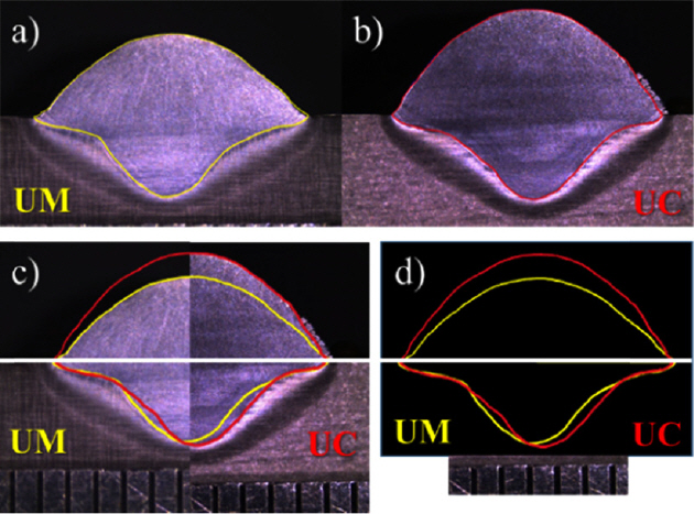
Fig 3(a) and 3(b) present cross-sectional macro images of the UM and UC with a highlight along the borderline of the single bead. The merged images are delineated in 3(c) and 3(d) for comparison. There was little difference in the width and penetration depth of the single beads, while the height was highly different, as shown in 3(c) and 3(d).
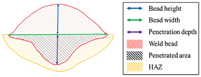
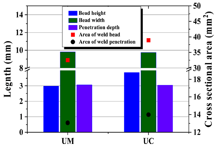
For a specific comparison, a detailed analysis was performed using measuring software. The measurements were taken for the length of the bead height, width, and penetration depth, as well as the area of the actual weld bead and weld penetration, as illustrated in Fig 4 with a schematic diagram. Table 3 lists the measured values of each sample, which are also plotted in Fig 5.
The macro image comparison in Fig 3(d) showed that the difference in the bead width, penetration depth and the crosssectional area of the weld penetration in the UM and UC was not significant, as was also described in Table 3 and Fig 5. Terner et al. [13] examined the influence of the shielding gas as a single parameter on the GMAW of E-7012 solid wire on the mild steel and found that the M21 and C1 shielding gas produced a similar bead geometry. However, in this research, the height was approximately 30% higher in the UC than the UM. As a result, the cross-sectional area of the weld bead increased with increasing bead height despite the width and depth are similar. In practice, the increase in bead height resulted in a 19% larger weld bead cross-sectional area in the UC. CO2 gas is efficient with respect to the filler metal deposition rate, and is prone to produce a convex bead shape that can be seen over the weld. Whereas the Ar based mix gas tends to make a comparably flat bead [7]. Generally, a convex shape bead is not preferable in a typical fillet or lap joint GMAW. On the other hand, it can be advantageous for the GMAW-based WAAM process, shortening the lead-time of a product by decreasing the number of passes.
4.2 Small-scale (3 x 3) additive manufacturing
4.2.1 Visual inspection
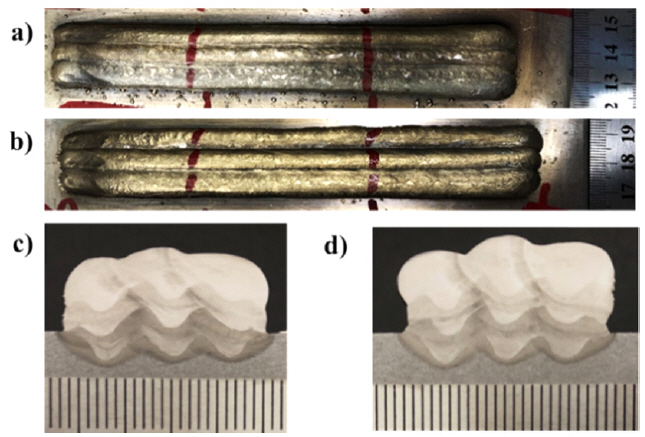
The small-scale (3 × 3) AM was conducted with nine passes, as shown in Fig 6. The surface conditions were different in the two samples, as discussed in Section 4.1.1. The surface contamination by the weld scale was observed in the UM as shown in 6(a), while the surface of UC was free of sessile weld scale, as shown in 6(b). Furthermore, as shown in 6(c) and 6(d), the height and volume of the final product were larger in the UC, as discussed in Section 4.1.2. The width of the UM and UC were measured to be 21.89 mm and 22.73 mm, and the heights of those were 11.32 mm and 12.73 mm, respectively. This agrees well with the hypothesis that the bead formation behavior of UC would be advantageous to the productivity of the WAAM process, as discussed at the end of Section 4.1.2.
4.2.2 3D-CT analysis
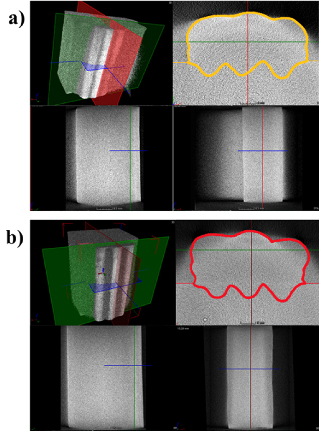
A defect, such as porosity, can be formed because a surface contamination reacts with the gases, moisture, or weld puddle. Porosity is a common defect in welding, and as a crack initiation point it can be a weak point for the product [3]. Therefore, the formation of porosity in the weld beads or AM products should be avoided. The 3D-CT analysis was conducted to determine whether porosity formed in the AM product, as shown in Fig 7. It is shown with the boarder lines to help to distinguish the AM product from the results. It was thought that the porosities were formed in the UM due to the surface contamination by the sessile weld scale, but none were observed.
4.2.3 Bead geometry
The cross-sectional areas of each sample were measured, as shown in Section 4.1.2, and the results are shown in Table 4. The cross-sectional area of the weld bead in small-scale AM approximately 19% larger in the UC, while the cross-sectional areas of the weld penetration were similar. Fig 8(a) presents the highlights of the borderline of the cross-section of AM products for the intuitive comparison, as described in Fig 3. The cross-sectional area of the weld bead in the UC was larger than that of the UM, as shown in Fig 8(b), using a merged image of the highlights.
In view of the regularity of AM, it can be seen that the UM shows better performance than the UC. This might be due to the higher bead height and larger amount of deposition of the UC. In Fig 8(c), the designated AM passes based on the highlights of BOP in Fig 3(d) are described within the highlights illustrated in 8(a) and 8(b). From the second layer, there are gaps at both ends of the bead and between each layer. The gaps are formed because of the difference in the shape of the surface where the AM was performed. The AM of the first layer was performed on the flat surface of the substrate, while the following layers were performed on the previous weld beads, with its hills with deep valleys on each side, thus forming gaps. Because the weld bead is initially a melted pool, it flows down to fill the gaps by the gravity. Consequently, the comparably uneven surface at each side of the UC could have resulted from the nature of bead formation, which has higher hills and deeper valleys than the UM. However, it was not significant enough to consider it a collapse or side collapse, which is a typical WAAM defect [14, 15].
4.2.4 Micro vickers hardness
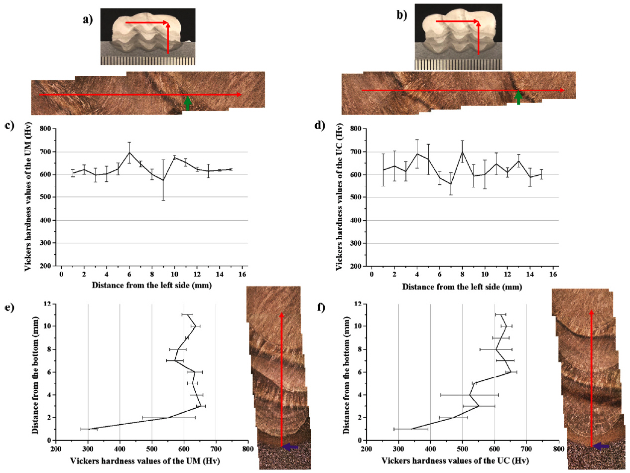
The shielding gases influence the microstructure as well as the mechanical properties of the weld, e.g., strength, toughness, hardness, and corrosion resistance [3]. This is mainly due to the interactions with the substrate (or prior weld bead) and the filler metal during the arcing and post-arcing stage. Terner et al. [13] reported that the different shielding gases have a significant impact on the hardness of the weld bead. Therefore, the micro Vickers hardness tests were conducted to determine the effect of the shielding gas on the micromechanical property of the WAAM along the horizontal and vertical direction, as shown in Fig 9(a) and 9(b). Fig.9(c) and 9(d) show the hardness values of the deposited metals in a horizontal direction, while Fig 9(e) and 9(f) show that of in a vertical direction which covered the pure HAZ near the substrate in the UM and UC. The average values of the overall deposited metal of the UM and UC were 620 ± 51 HV and 600 ± 66 HV, respectively. Meanwhile, the hardness values of HAZ near the substrate (Fig 10(c) and 10(d)) were measured as 350 ± 73 HV and 383 ± 84 HV, whereas the hardness of the substrate was 202 HV.
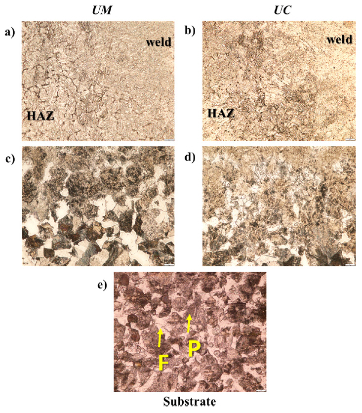
Further, the microstructure images of the green and purple arrowed regions in Fig 9 are shown in Fig 10 as well as that of the substrate. The microstructures of both are dominated by the martensite and bainite, while the allotriomorphic ferrite along the prior austenite grain boundaries is observed in the multiple HAZ as shown in Fig 10(a) and 10(b). Both the UM and UC showed hardness values of over 500 HV. This would be mainly due to the WAAM process feature, where the AM products are composed like all-weld-metal.
In the pure HAZ near the substrate, the mixture of martensite and/or bainite, pearlite and ferrite were observed as shown in Fig 10(c) and 10(d). It can be thought that the α → γ → α allotropic phase transformation has occurred in this region, and it might cause the higher hardness in the HAZ than the substrate which consisted of ferrite and pearlite as shown in Fig 10(d). The higher fraction of pearlite and the coarser grain size in the UM resulted in a slightly lower hardness than the UC. Although the micromechanical properties of the UM and UC were different, it was not significant considering the deviation values were over 50 HV. This might be due to the high percentage of CO2 gas in the M21, which agrees with the results reported by Terner et al. [13] that the weld beads with M21 and C-C (C1 in this paper) had equal hardness. In this research, also, the hardness values and dominant microstructural constituents of the UM and UC products were similar. This implies that the shielding gas itself did not have much critical impact on the microstructural evolution from a macroscopic viewpoint.
4.3 Large-scale two-dimensional additive manufacturing
4.3.1 Visual inspection
A large-scale AM was conducted to observe the additive manufacturability of massive products. The large-scale AM products were well manufactured at five per substrate, which was fixed by the clamps, as shown in Fig 11. Both the UM and UC were additively manufactured with a length and height of approximately 125 mm. The UM products required 64 passes to cover the designated height of AM, whereas the UC needed only 57 passes. This agreed well with the results and discussions in Sections 4.1.2 and 4.2.3. The walls were manufactured uniformly, but the side collapsed at the start point of some layers in both the UM and UC. This was caused mainly by an excessive heat sink, heat input, cooling rate, or melted metal in the weld pool [14, 15]. Among these, excessive melted metal in the weld pool could be considered to be dominant because the UC cases had a higher bead height and a broad cross-sectional area, which meant a larger amount of the melted metal in the weld pool. Therefore, this was observed more in the UC products than the UM. On the other hand, it was not critical to the precision of the product from the viewpoint of manufacturing the AM component, because it was observed only on the few start points, which are the portions cut out by machining to make the final product. Other typical defects, such as portions of unmelted wire stuck on AM products, or large distortions due to the heat accumulation, were not observed [14].
4.3.2 Internal defect
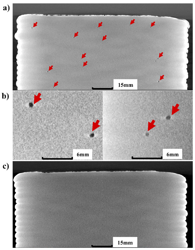
As discussed in Sections 4.1.1, 4.2.1, and 4.2.2, the sessile scale was observed on the surface of UM products. This could be due to the different chemical reactions between the material and gas, and could result in the formation of porosity, which can degrade the strength and fatigue life [7, 10, 11]. Therefore, the 3D-CT analysis was conducted to determine if the internal defects were formed in large-scale AM products. Porosities were observed in all UM products (Fig 12(a) and 12(b)), but not in the UC products (Fig 12(c)). The porosity in the UM was less than 1 mm in size, and their locations were random. Two reasons for the differences in internal defect formation behavior can be considered, as follows.
i) According to previous research [3, 10, 11], the sessile weld scale on the surface could be the main reason for the formation of porosity, as surface contamination, which was mentioned in Section 4.2.2. But in the UC, there was no sessile weld scale on the surface and the porosities were absent. Hence, it is reasonable to consider that the surface contamination by the weld scale observed in the UM was responsible for the formation of internal defects, which are observed as porosity. The surface conditions might differ due to the different chemical reactions between the weld pool (or solidified surface behind the weld pool) and each of shielding gasses [8, 12].
ii) The different gas properties might be another reason for this. The thermal conductivity and specific heat of two different kinds of shielding gases used in this research were different. This results in different heat intensity and arc behavior. Consequently, those differences can produce different peak temperatures, arc force, Marangoni flow, etc [8, 16]. If the flow in the weld pool is insufficient to blow out the bubbles, the gas could be captured as porosities at arbitrary locations.
4.3.3 Tensile shear test and fractography analysis
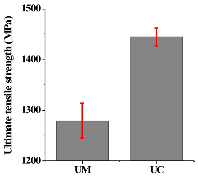
Tensile shear tests were conducted to evaluate the mechanical property of the UM and UC products, and the results are plotted in Fig 13. It can be seen that the ultimate tensile strength (UTS) of the UM and UC products were rated as 1270 and 1450 MPa, respectively. The difference between two groups of samples were more than 200 MPa, even though the hardness values and dominant microstructural constituents were not significantly different, as discussed in Section 4.2.4. To find out why, a fractography analysis was conducted using SEM.
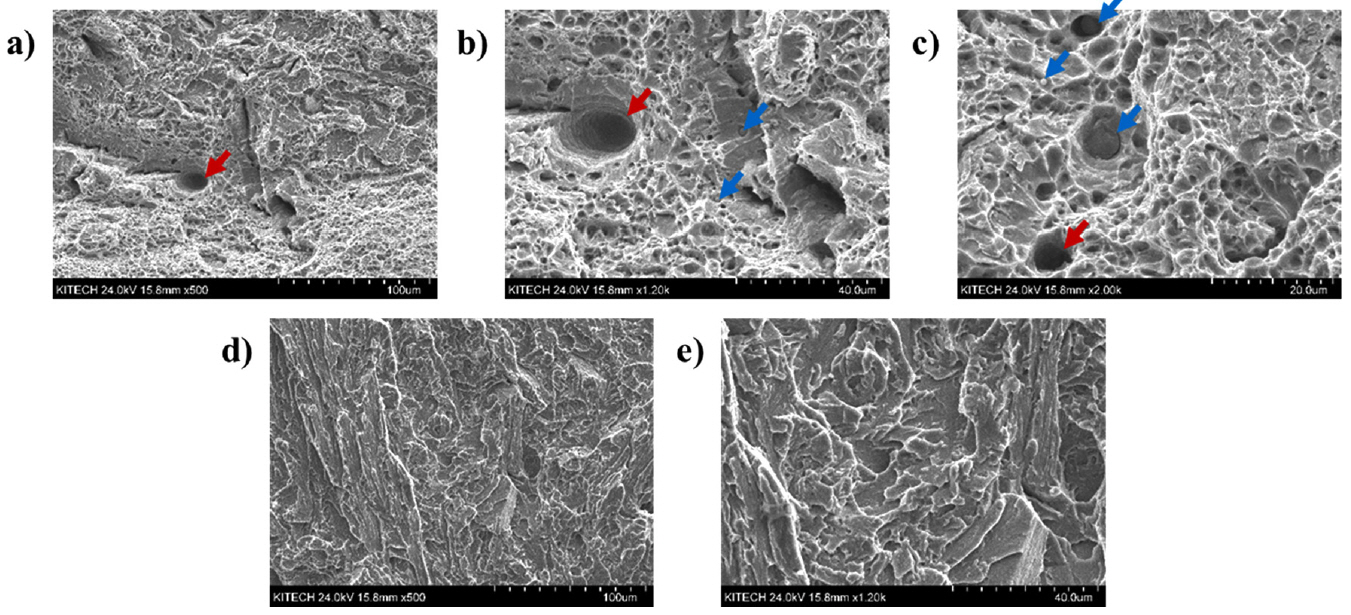
Both the UM and UC samples exhibited transgranular fracture surfaces in Fig 14(a) and 14(d). While the UM showed a dimpled transgranular fracture with the presence of porosities and micro-voids, but the UC showed clear cleavage. In Fig 14(b), the porosity and also the large numbers of spherical shaped particles (precipitates and/or inclusions) were observed, as pointed out with red and blue arrows, respectively. The possible reasons for the formation of porosities were discussed in the previous Section, and it is well known that these degrade the mechanical properties of the product [3].
On the other hand, the large numbers of particles were observed in Fig 14(b) and 14(c) could be mainly MX carbides such as M23C6, M7C3, M2C, etc. [12, 17-18]. The material itself has a high fraction of Cr and Mo with little Ti, and it is well known that those alloying elements have a high chance of forming carbides by the depletion from the matrix [17-18]. These precipitates could act as unexpected crack nucleation sites and induce the dimpled transgranular fracture as shown in Fig 13 and 14(a) [19-22].
Consequently, the porosities and precipitates in the UM can be considered detrimental to mechanical properties. Meanwhile, in Fig 14(d) and 14(e), it is notable that the UC has almost none of the precipitates which were observed in the UM. It might be due to the different arc properties and consequent thermal histories induced by the different shielding gasses [8, 16]. As seen in previous Sections, the cross-sectional area of the UC was higher than the UM. This means that the heat intensity is higher in the UC cases, and it directly related to higher heat input, even though both cases using the same current and voltage. It is well known that the higher the heat input, the higher the cooling rate of the weld [12]. In addition, the depletion of alloying elements from the matrix and formation of precipitates is dominated by the time and temperature [17-18, 23]. Thus, it is reasonable to consider that it is possibly related to the extremely low number of precipitates in the UC.
This phenomenon implies that the shielding gas has an effect on the depletion of alloying elements and the formation of precipitates from a microscopic viewpoint, with little impact in the macroscopic viewpoint as discussed in Section 4.2.4. Further in-depth research is in progress to find out the reason for this phenomenon.
5. Conclusion
This study examined the additive manufacturability of commercial 5 Cr – 4 Mo tool steel repairing solid filler wire on a thick SCM 440 (AISI 4140) substrate. The AM was based on the GMAW process with two different shielding gases, M21 and C1. The criteria used were geometrical information from the BOP and AM products, as well as internal defects and mechanical properties. The conclusions derived in this study were as follows:
i) Sessile weld scale was observed on all UM products, but not on the UC products. As surface contamination, it adversely affected the performance of the product, and was attributed to the use of inappropriate shielding gas for the material.
ii) Internal defects were found as the shape of porosity in UM products. The surface contamination by the sessile weld scale could be critical to forming defects, especially the porosities within the product.
iii) A higher bead height and larger cross-sectional area was consistently observed in the UC compared with the UM in three different types of tests. A larger amount of deposition could be advantageous to the AM process because it becomes to make the products with less effort and time.
iv) The main microstructural constituents and the micromechanical properties of the UM and UC were similar. But the UTS differed by more than 200 MPa. The porosities and the larger amount of precipitates in the UM degraded its tensile strength.
v) It can be suggested that the shielding gas has an effect on the depletion of alloying elements and formation of precipitates from a microscopic viewpoint, while having little impact on the dominant microstructural constituents from a macroscopic viewpoint.