


1. INTRODUCTION
Reducing carbon dioxide emissions from fossil fuel consumption is now the policy of every government worldwide. Conventional coal fuel power plants must now be decommissioned because of the environmental issues they cause. But extending the life of a power plant by replacing traditional coal fuel with a clean fuel is also an option. Many studies have also investigated ways of improving the components of domestic power plants, for example, by using heat resistant alloys, advanced boiler tubes and monitoring systems, to repair and extend the life of such plants. But before they can be applied and further commercialized, the reliability of locally developed products must be verified by field demonstration testing. For this purpose, a clean power test-bed plant was set up in Korea [1].
Heat resistant alloys for boiler components have been locally developed over the past five years in Korea. However, demonstration tests were delayed because there was no facility to conduct quality assessment. The objectives of this work were to design, manufacture, erect and operate a component test facility so that the locally developed tubes could be evaluated in a test-bed plant. The study also included setting up a database for quality and reliability, and test procedures for the tubes. The locally developed tubes were the T11, T22 and T91, which are commonly used at a steam temperature below 550 °C. The host plant for the demonstration test was the Youngdong #2 unit, which is a coal-fired plant with a steam temperature of 541 °C, a maximum pressure of 174 kg/cm2 and a maximum output of 200 MW.
2. EXPERIMENTAL PROCEDURES
2.1. The scope
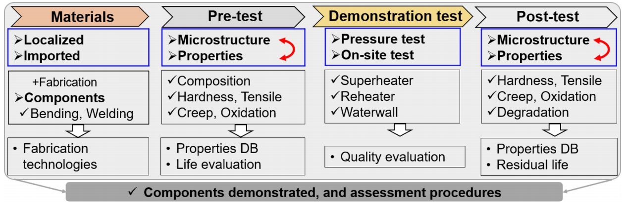
Figure 1 shows a schematic of the demonstration test procedures for the locally developed boiler tubes, composed of three assessment items: a pre-test in the laboratory, a field demonstration test and a post-test in laboratory. Both locally developed and imported (original used) tubes were used to manufacture the boiler components. The processes generally included bending, welding, post-bending, and post welding heat treatment. The pre-test in the lab included analysis of both microstructure and properties, i.e., chemical composition, hardness, tensile strength, and creep, etc.
Before the demonstration test, the fabricated components needed to pass water pressure tests, both before and after being installed in the boiler [2]. The demonstration test components also needed to provide the same level of performance as the original components, and not fail during operation. After a period of operation, parts of the components were removed and post-tested in the lab to examine their microstructure and material properties. Through all of the processes, the manufacturing technologies in particular, the properties database, quality evaluation and reliability results of the boiler tubes and components could be drawn out. Finally, the procedures for demonstrating and testing the locally developed boiler tubes were applied.
2.2. Test criteria and requirements
The ASME Boiler and Pressure Vessel (B&PV) code covers most of the test items and requirements for materials and components, as shown in Table 1 and Table 2 [2]. The basic items of appearance, dimensions, chemical composition, hardness, tensile properties, and grain size are always included in the “Inspection Certificate” by the tube makers. In addition, the manufacturer of the boiler components supplies evaluation data on the hardness and macro/micro-structure of the bent and welded components, as well as the water pressure acceptance reports [3]. However, no code or requirements are provided for long-term creep properties. Despite this, creep degradation is the dominant reason for failures in power plants, so obtaining creep and microstructural stability data are critical to safe operation [4,5]. Based on this experience, Table 1 and Table 2 list additional criteria, such as precipitates and creep properties suggested in this work. The requirement of the creep properties is that the test results need to be equivalent to other makers, namely, the original imported tubes.
The high temperature properties of boiler tubes are determined based on their microstructural stability [4,5]. For low-alloyed T11 and 22 tubes, the matrix must be composed of ferrite and pearlite, and the fraction of pearlite should be the same as in the tubes of other manufacturer. The precipitates reported in T11 are M3C [6] and M2C [7], and in T22 were M2C, M7C3, M3C and M23C6 [8]. Most of the precipitates form “in situ”, or during fast transition to the final equilibrium state of M23C6 during heat treatment, aging and creep, as suggested in [8,9]. In the present work, there is no specific requirement regarding the types of precipitates in T11 and T22.
For the high-alloyed T91 tube, the matrix should contain tempered martensite with a substructure of lath, micropockets, subgrains, and dispersed M23C6 domains in the grain boundary (G.B.), and lath and pocket G.B. [4,10,11]. Because the chemical composition contains a strong carbide former such as V and Nb, tiny MX type precipitates always form within the grain interior. However, this type of precipitate is very stable [4] during service and creep, so no specific requirement is given. Apart from types of precipitate, quantitative data on the size and fraction of the precipitates is important to creep properties, so the locally developed tubes should also have the same features as those of other manufacturer.
2.3. Pre-test methods
ASME A30, E8, E21 and E112 provide several standards and methods for testing metals. In our study, the test methods followed the standards for boiler tubes. We specifically note some of the key detailed parameters. Using Spark-Optical emission spectroscopy, we conducted chemical composition measurements five times on the tubes until the results of each element became stable. We conducted microstructural evaluation of the tubes using a (radial) direction cross-section, and observations by scanning electron microscopy (SEM) and transmission electron microscopy (TEM) to study the grain size and precipitates. Grain size measurements were conducted at the steam-, center-, and fire-side regions of the tubes. Precipitate type and other features were measured using SEM and TEM. Vickers hardness was measured along the cross-sectional direction, generally at intervals of 0.5 mm from the steam side to the fire side. Tensile and creep specimens with a diameter of 6 mm and gauge length of 25 mm were made from the drawing direction of the tubes. In addition to the room temperature tensile tests, samples were also tested at high temperature >500°C. At least three specimens were measured in each condition. We conducted constant stress creep tests on the tubes and compared the results with the current widely acceptable data from the National Institute of Materials Science (NIMS).
2.4. Demonstration test
The boiler components were fabricated with tubes using bends and welding. The tubes were locally developed by ILJIN Steel Corporation (ILJIN) in Korea and imported from Nippon Steel & Sumitomo Metal (NSSMC) in Japan. The test components needed to be designed to fit the boiler parameters of the Youngdong #2 unit. One goal was that plant operation should not be affected. The concept was to replace part of the waterwall (W/W) and superheater (S/H) with the test components during repair construction of the secondary S/H during an overhaul period in 2017. Table 3 lists the tubes used and the entire demonstration plan.
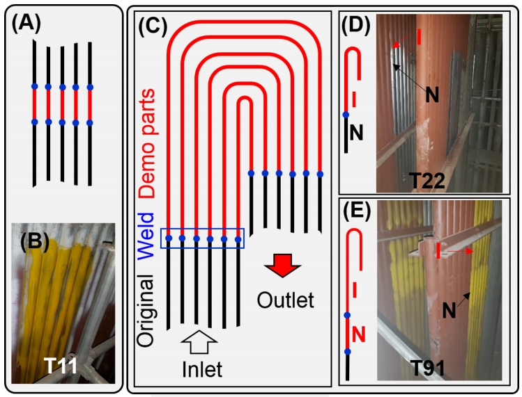
The locally developed T11 tubes were tested in the W/W, and 10 pieces of tubes with a 1 m length were used to replace the original carbon steel of A210-A1, as schematically shown in Figs 2A and 2B. Localized T22 and T91 components were tested in the secondary S/H, which replaced the original imported T22 tubes, as shown in Fig 2C. Six rows of T22 tubes included bends, and the welded parts were welded into the 9th and 10th bundles (9B and 10B) of the No. 5 manifold (Fig 2D). For T91, the test components were composed of locally developed and imported tubes, and the 1 m length NSSMC tubes were welded to the ILJIN tubes. Similarly, six rows of T91 tubes included bends, and the welded parts were welded into the 24th and 25th bundles (24B and 25B) in the No.12 manifold (Fig 2E).
Note that, theoretically, spare parts should be manufactured for the test components in case accidents occur during operation. However, this was not done because they were replaced with the same T22 grade tubes, and even grades with higher properties of T11 and T91. In addition, it is known that failures involving cracks always appear in joint points with dissimilar welds, such as the austenitic and ferritic tubes [12], while the proposed weld points were only on ferritic tubes. The operating conditions of the steam in the W/W were 382 °C and 195 kg/cm2 and they were 541 °C and 174 kg/cm2 in the secondary S/H.
2.5. Post-testing of the demonstrated tube
After 13,000 hours of operation, the main parts of the components were remained for service for even long time. Several tubes that included weld joints were cut and post-tested in the lab. Table 3 lists the position and quantities of samples taken from the demonstrated tubes. None of the bent areas were cut out of the components, because the sampling time was too short during the boiler overhaul period. The cut tubes were evaluated for their microstructural and mechanical properties.
3. RESULTS AND DISCUSSION
3.1. Pre-test in the lab
3.1.1. Chemical compositions
Table 4 lists the chemical compositions, requirements and the measured results of the tested tubes. The concentrations of elements in the alloys of the three types of tubes were consistent with code requirements. For T11 and T22, the concentrations of C, P, and S were very close to the imported values, while Cr elements were slightly higher (0.2%), with a very small amount of Nb and Al elements. There was a similar trend for the T91 tubes, in which Cr was 0.36% high than in the imported tube.
3.1.2. Hardness and tensile strength
Table 5 lists the microhardness and tensile strength requirements, and the measurement results for the test tubes. It can be seen that all of the hardness values of the locally developed tubes were within the code requirements. T11 and T22 had a very similar hardness, of 152~157 HV, and the locally developed tube was about 20 HV higher than that of the imported tube. Moreover, the hardness of the locally developed T91 was 14 HV higher than the imported tube. The I/N ratio is also shown in the Table, and it is clear that the hardness of the locally developed tube was the same level as the imported one.
Room temperature (RT) and high temperature (HT) tensile properties were measured, as shown in Table 5. The temperature for T11 and T22 was 500 °C, while for T91 it was 550 °C. For the T11 tubes, the RT tensile properties were within the code requirements. At RT, the yield strength (YS) and tensile strength (TS) of the ILJIN tubes were 20 MPa higher and 18 MPa lower than those of the NSSMC tube, respectively. At 500 °C, the YS and TS of the ILJIN tubes were 22 MPa lower and 22 MPa higher than that of the NSSMC tube, respectively. The elongation (e) of the ILJIN and NSSMC tubes was almost the same at both RT and HT. For the T22 tubes, the YS and TS of the ILJIN tubes were higher than that of the NSSMC tube both at RT and HT, and the YS was as high as 91 MPa at RT. This was probably due to the slightly higher Cr concentration and finer grain size of the ILJIN tubes.
For the T91 tubes, the YS and TS of the ILJIN tubes were 12 MPa lower and 39 MPa higher than those of the NSSMC tube at RT, respectively. The YS was 10 MPa lower than that of the imported one at HT. The I/N ratio of the tubes’ tensile properties are also given in the table. Most of the values were over 91%, which suggests that the locally developed tubes had the same levels of tensile properties as the imported tube, and in the case of T22, had even better properties than the imported tube.
3.1.3. Creep strength
Determining the creep strength of boiler tubes is a key way to evaluate the properties of their material during high temperature service. Establishing the creep life data of boiler tubes is necessary to determine their application in power plants. The tubes manufacturers and a third institute were used to test the long-term creep rupture properties of their products with different heat and different processes. The data from third party testing is preferred for power plants.
Figure 3 shows the creep rupture life of the test tubes, compared with the data from the NIMS creep data sheet [13]. The creep temperature of T11 and T22 was 500 °C, and for T91 it was 550 °C and 600 °C. NIMS had the same data points for the same grade tubes at the same test conditions with different products, which are replotted with the lower and upper lines in Fig 3. Note that the variation in the time to rupture of the different products under the same conditions was quite wide, in particular for the T22 tubes, where the upper line was 10 times longer than the lower line.
As shown in Fig 3A, the time to rupture of the ILJIN T11 was within the range of the NIMS creep data sheet. The T11 tube is to be demonstrated at the position of the W/W and to replace the lower grade of the A213-A1 carbon steels, therefore, the creep properties are supposed to qualify under the requirements. For the T22 tubes, the time to rupture was between the lower and upper line of the NIMS data, as shown in Fig 4B.
More efforts were carried out on the T91 tubes, since they always need to be designed for the higher temperature part of the boiler. The times to rupture of both the ILJIN and NSSMC tubes at 550 °C and 600 °C are shown in Fig 3C. It can be seen that most of the test points obtained here were between the upper and lower line of the NIMS data. In addition, the time to rupture of the ILJIN tube was longer than that of the NSSMC tube at both test temperatures, suggesting that the locally developed tubes have even better creep properties than the imported ones.
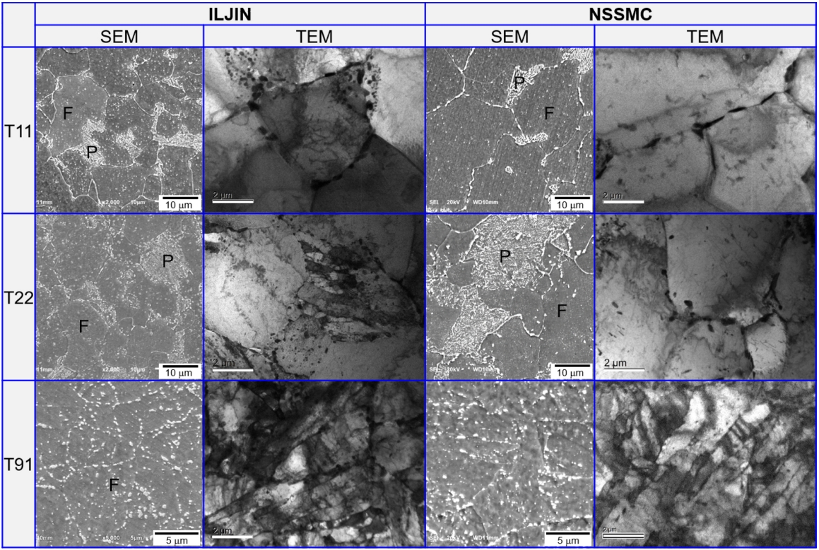
3.1.4. Microstructure
Figure 4 is a set of SEM and TEM images of the T11, T22 and T91 tubes used in the demonstration test. It can be seen from the SEM images that the matrix of the T11 and T22 tubes are ferrite and pearlite, while the T91 has a ferrite structure. The ferrite and pearlite structures are respectively noted by F and P in the micrographs.
More grain boundaries can be easily found in the SEM micrographs of the ILJIN tubes, which suggests that the prior austenite G.S. (PAGS) of the locally developed tubes were finer than the imported one. In addition, tens of SEM images at lower magnification were used to measure the average G.S. and the results are shown in Table 6.
The G.S. of the locally developed tubes of T11 and T22 were ~10 mm smaller. The G.S. of T91 was similar to that of the imported tubes. In addition, a larger quantity of white spots can be observed in the SEM micrographs, dispersed throughout the structure. A closer observation is shown in the corresponding TEM images, in which the precipitates are dispersed at the grain boundaries (G.B.) and grain interior (G.I.). These precipitates may be the M2C and/or M3C in the G.B. and within the pearlite grains in the T11 steels, as suggested in the literature [6,7]. The domain precipitates dispersed in the G.B. of T22 may be the M23C6, while M3C and M7C3 are in the pearlite grains, and the M2C is in the ferrite grain, as suggested by Yang [8].
In the T91 steels, the domain precipitates are supposed to be M23C6 [4,5,11], which is dispersed throughout the microstructures, as shown in Fig 4. The features of all the precipitates were measured in tens of TEM micrographs for both the ILJIN and NSSMC tubes. The results are shown in Table 6. It can be seen that the average size of the precipitates in the locally developed tube was finer than in the imported tube, and the area fraction of both types was at the same level. These investigations confirmed that the microstructures of the locally developed tubes were within the code requirements, and had the same level as the imported ones.
3.2. Demonstration test
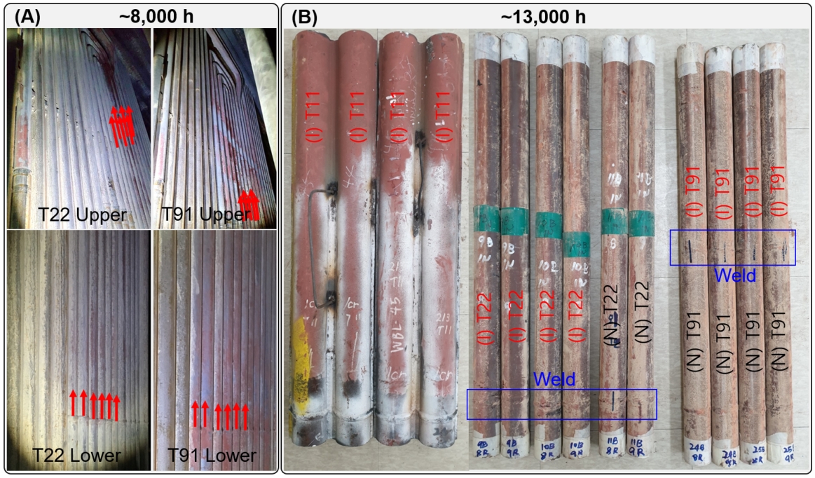
The demonstration operation began in July of 2017 at the coal-fired boiler of Youndong unit #2. After about one year of safe operation, visible examinations were carried out during the overhaul period in June of 2018. All areas of the bent and welded parts were examined, from the lower to upper positions in the bundle. Typical images are shown in Fig 5A. The test tubes are noted by red arrows. No failures or deformation were observed, and the components look just as they were when originally installed. Safe operation continued to the end of December 2018. At the beginning of 2019, re-construction of the boiler began for fuel transformation from coal to biomass. During the construction period, only parts of the tubes were cut from the test components, and most of the parts were allowed to remain for long-term operation/testing with the biomass fuel. Figure 5B shows the cut tubes of the demonstration test tubes after ~13,000 h; no cracks, failures, or any other defects were found in the tubes.
3.3. Post-test after demonstration
Table 7 shows the evolution of tensile properties, and the thickness of scale in the tubes after 13,000 h of the demonstration test. As shown in Table 7, the degradation ratio of the tensile strength of the locally developed T11 tubes (ILJIN) was below 3% both at RT and HT. This suggests that the T11 tubes weren’t degraded after the short-term demonstration test, which is most probably due to the low temperature (382 °C) of the steam in the W/W.
The tensile properties of the T22 and T91 tubes decreased after the demonstration test. For the T22 tubes, the tensile properties of the ILJIN and NSSMC tubes after demonstration were almost the same at both RT and HT. However, the YS degradation was as high as 38%, while the TS and e remained relatively stable (<7%) when tested at RT. The degradation ratio of the ILJIN was 20% larger than that of the NSSMC tube, probably due to the high YS of the locally developed tube. In the HT tensile test, the YS and TS properties decreased with the e enhancement to almost the same level. In the RT tensile test, the YS of the weld components was 25% away from the base tubes, and the TS was as high as the base tubes. At HT, it is possible to say that the weld components had the same level of tensile properties as the base one. The greatest degradation in the weld components was the decrease in e (>64%). This is believed to have occurred because the weld metal was not significantly deformed during the tensile test. The position of the tensile fracture in the weld components appeared in the heat affected zone (HAZ) in the ILJIN parts of the test specimens.
For the T91 tubes, the tensile strengths (YS and TS) of the locally developed and imported tubes after the demonstration were almost the same at both RT and HT. However, the ratios of the e of the ILJIN tubes with those of the imported one at RT and HT were 75% and 87%, respectively. Degradation of the tensile properties (YS and TS) of the ILJIN and NSSMC tubes were found to be at the same level, with ratios below ~18% and ~12% at RT and HT, respectively. In addition, the ε degradation in the ILJIN tube was higher than that of the NSSMC tube.
For the weld components of the T91 tubes, the YS and TS of both the locally developed and imported tubes were higher (~17%) than that of the base tubes at RT, while they were lower than the base tubes (~18%) at HT. Obviously, the ε decreased as much as 39% in the weld components of the imported tubes. The position of the tensile fracture in the weld components appeared in the HAZ in the imported parts of the test specimens. Compared to the T22 tubes, the slight degradation in the T91 tubes is believed to be the reason for the relatively low steam temperature of 541 °C.
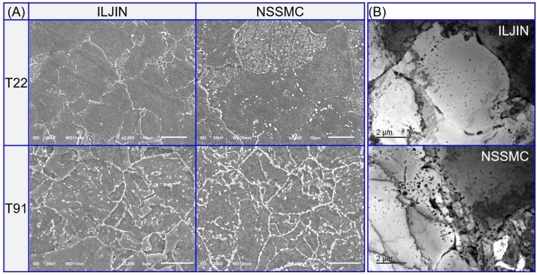
Figure 6 is a set of SEM and TEM images of the T22 and T91 tubes after the demonstration test. The SEM images show that the PAG size did not change too much compared to the new one (Fig 4), in both the T22 and T91 tubes, while the fraction of precipitates within the pearlite, as well as the pearlite content, decreased in the T22 tubes. Meanwhile, the dislocation density decreased significantly in the demonstration tested tubes, as shown in Fig 6B. This indicates the grains recovered during the high temperature exposure. For the T91 tubes, a number of independent precipitates can be observed in the grain boundaries of the new tubes. They appeared continuously after the demonstration test (Fig 6A), indicating a slight coarsening of the precipitates.
It is known that the degradation of properties in the low alloyed T11 and T22 is related to decomposition of the pearlite structure, complex carbide transformation, and grain recovery during high temperature exposure [13]. Meanwhile, the formation of the Laves phase, the coarsening of domain precipitates, and grain recovery are the main mechanisms found in the T91 tubes upon high temperature exposure [4,5,11,14]. These factors may explain the decrease in the base tube tensile properties in T22 and T91 after the demonstration test, to a certain extent. A quantitative analysis of the mentioned microstructure features is currently under study, and will be matched with the properties, to finally determine the degradation mechanisms of the T22 and T91 upon exposure in field conditions.
In addition, the scales formed on the steam side were measured in the cut tubes, and the average thicknesses are shown in Table 7. A very thin oxide scale (~10 mm) was observed in the T11 tubes. For both the T22 and T91 tubes, the thickness of the scale formed on the ILJIN and NSSMC tubes after TDM was almost the same. These results suggest that the oxidation resistance of the locally developed tube was the same as the imported tube.
The creep properties of the test tubes, and in particular T22, decreased significantly after the demonstration test. As of the writing of this paper, most of the creep test samples had not ruptured. A further report will focus on the degradation mechanism of creep life, and the corresponding microstructural evolution.
3.4. The test standard
Based on the pre-test, demonstration test, and post-test, we developed a “test procedures for boiler components for testbed demonstration”. The contents include all of the items and criteria, and at the time of this writing, it is under consideration for standardization by a third institute.
4. CONCLUSION
This work conducted demonstration tests of boiler tubes in a clean power test-bed plant. The testing included a lab-based pre-test, a field demonstration and a lab-based post-test. Three types of locally developed tubes, T11, T22, and T91, were tested and compared with the original imported tubes.
1) The pre-test in the lab included an assessment of the tubes’ microstructure and mechanical properties. The results confirmed that the chemical composition, microstructure, hardness and tensile strength of the locally developed tubes met the code requirements and had the same levels as the imported tubes. Moreover, we confirmed that the creep properties of the locally developed tubes were within the ranges of the NIMS reported database. These results suggest the potential outcomes of the field demonstration test.
2) The demonstration test was carried out in the boiler of Youngdong unit #2, where parts of the waterwall (T11) and the superheater (T22, T91) were replaced with the newly manufactured boiler components, which were fabricated by bending and welding locally developed and imported tubes. The demonstration test period was 13,000 h, and no component failures were reported during operation. Afterward, parts of the tubes were cut out for the post-test, and the remaining components were allowed to continue operating in the test for even longer periods.
3) The post-test in the lab included the same items as the pre-test. The evaluation results showed that there was no significant change to the hardness of any of the three types of tubes. The degradation ratio of the tensile properties of the locally developed tubes was higher than that of the imported tube, but after the demonstration their properties were the same as the imported tube. In addition, the steam oxidation resistance of the locally developed tubes was found to be the same as the imported tube.
This work provides guidelines for test procedures of locally developed tubes for demonstration. The test results will be useful to enhance and improve the reliability of the properties of locally developed boiler tubes.