


1. INTRODUCTION
There have been several studies thus far utilizing graphene as a filler to improve the mechanical, electrical, and thermal properties of polymer and metal matrices [1-15]. To maximize the contribution of graphene to the thermal conductivity (TC) of a matrix, it is well known that in addition to a well-ordered alignment and uniform dispersion, a continuous graphene network in the matrix is also essential [16,17]. These conditions are key to improving the TC of graphene/metal composites while simultaneously minimizing interfacial thermal resistance along the alignment direction [18-20]. In addition, an understanding of C diffusion in Cu and its behavior at the Cu/C interface is fundamental to developing successful strategies for improving the performance of graphene-metal matrix composites [21-24].
Despite the extensive research on the subject, current fabrication methods for graphene-metal matrix composites involve complicated processes and expensive equipment, making the industrial use of these materials difficult. In a recent report, we introduced a simple in situ two-step fabrication route for a three-dimensionally interconnected graphene-networked Cu (3DiGn-Cu) composite with a curved shape, high aspect ratios and widths, and graphene platelets/sheets that are bent, anchored, and often wrapped around metallic grains at grain boundaries [25]. It has been known that graphene sheets, which have a large contact area with the metallic matrix, provide effective load transfer [26]. Additionally, the graphene wrapped around metallic grains in metal-graphene composites provides good corrosion resistance to the metallic matrix, with five- fold better stabilities in a corrosive environment compared to the metal without graphene [27].
As reported in our previous study [25], a 3DiGn-Cu composite was fabricated by a new and simple two-step fabrication route: axial compaction of Cu powder followed by chemical vapor deposition (CVD). In this work, we demonstrate the highest TC obtained thus far for the 3DiGn-Cu composite using compacted Cu power (99% purity) as a template for the growth of 3D graphene.
2. EXPERIMENTAL
2.1. Preparation of Cu discs
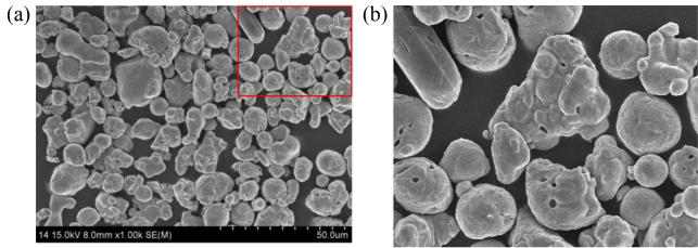
Cu powder (99% purity) was purchased from Aldrich and used as received. Scanning electron microscopy (SEM) images of the powder are shown in Fig. 1, with spheroidal particles of 14 ~ 25 μm in size. Figure 1 (b) is a magnified image of the box in (a) to show the pores on the particle surfaces. Without any additives, Cu discs (15 mm in diameter and 1.3 ± 0.1 mm in thickness) were prepared using 1.4 ± 0.15 g of Cu powder at different compaction pressures in the range of 1500 ~ 5000 kg. Axial compression was applied to the Cu powder in a mold using a double-action oil hydraulic press.
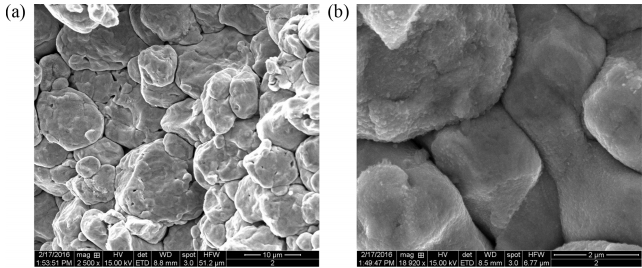
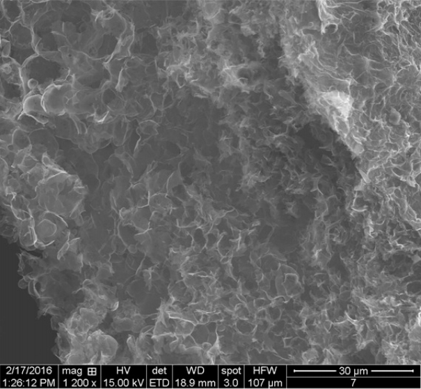
The SEM images in Fig. 2 show the exposed fractured surface of a compacted Cu disc sample after it was cut in half. The images show good mechanical interconnections between the Cu particles after compaction in a mold. In addition, the shape of the Cu particles, as shown in Fig. 2(b), changed from spheroidal to somewhat angular-shaped, which is an indication of the particles experiencing some degree of plastic deformation during compaction.
2.2. Synthesis of three-dimensionally interconnected graphene-networked Cu (3DiGn-Cu) composite
The CVD apparatus used in this work had a gas distribution system consisting of H2 (99.999%) and CH4 (99.995%) flowing through each mass flow controller into a quartz tube furnace 1.5 m long and 80 mm in diameter capable of reaching 1100 °C. The gas pressure inside the chamber was controlled by a throttle valve in conjunction with a pressure controller. The system controlled the furnace temperature to ± 0.5 °C at 1000 °C, gas flow rate to ± 0.05 sccm at 10 std. sccm, and system pressure to ± 0.01 Torr at 330 and 450 Torr. The temperature profile within the chamber when the furnace was set at 1000 °C was accurately determined by a single thermocouple moved down the length of the furnace, with measurements made at 2 cm intervals. A parabolic fit to the furnace temperature data gave an R2 value of 0.99.
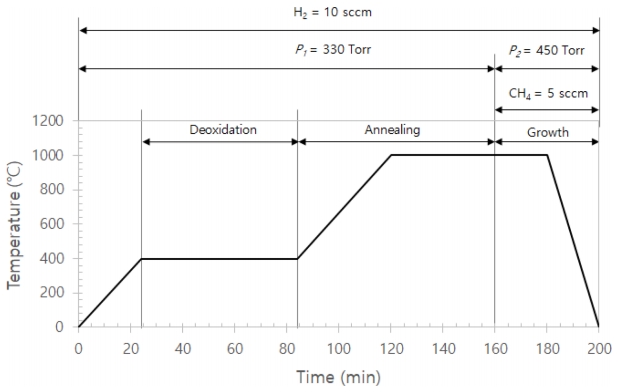
Cu discs on a sample boat were placed in the quartz tube in the middle of the chamber. Before starting, the chamber was flushed three times with Ar gas. The 3DiGn-Cu composites were synthesized following the experimental conditions shown in Fig. 3. The specimen was cooled at a rate of approximately 200 °C/min and was removed from the furnace when it reached to room temperature. The purpose of using H2 gas at 400 °C for 1 h in this experiment was to remove oxides and produce a high-surface-area Cu powder product that could react readily with carbon.
2.3. Thermal conductivity measurements
Accurate measurements of the thermal properties (thermal diffusivity and specific heat) and the mass of a sample are important for the eventual determination of its TC. The thermal diffusivity of the 3DiGn-Cu composite was measured using the NETZSCH LFA 447 based on a wellknown method. In this method, the front side of a planeparallel sample is heated by a short light pulse. The resulting temperature rise on the rear surface is measured using an infrared detector, according the Parker’s law [28]. By analysis of the resulting temperature-versus-time curve, the thermal diffusivity can be determined. Additionally, heat capacity is measured by a TA instrument DSC Q2000. The densities of the 3DiGn-Cu composites were measured using Archimedes principle with a special electronic scale (Mettler Toledo), and the densities of the compacted Cu discs were estimated by measuring their dimensions (diameter and thickness) and weights after Cu powder compaction. Therefore, the thermal conductivity (k) was calculated using k = αρCp, where α is the thermal diffusivity, Cp is the specific heat, and ρ is the bulk density of the sample.
3. RESULTS AND DISCUSSION
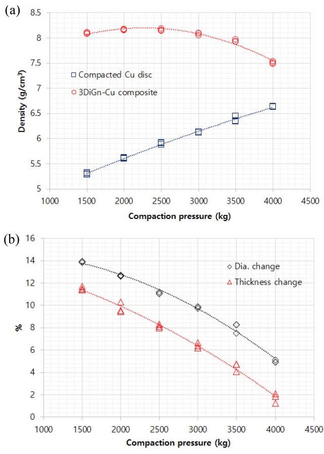
In addition to the changes in thickness and diameter, the densities of the three compacted Cu discs at each compacting pressure were estimated and compared to the measured densities of the 3DiGn-Cu composites after CVD, as shown in Fig. 4. To avoid any contamination during the synthesis of the 3DiGn-Cu composites, we did not use any lubricant for the particle compaction. During compaction at high pressures (2500 kg), the Cu particles at the disc surface experience relatively more plastic deformation than those inside the disc because of the friction force between particles. As a result, the particles of the discs compacted at higher pressures were less dense on the inside than at the disc surface. During CVD at 1000 °C, the particles grow to reduce the surface energy as a result of Cu diffusion. The inner particles have longer diffusion distances owing to their lower density, which leaves pores among them due to a lack of sufficient diffusion or sintering time. This explains why the densities and dimensional changes (diameter and thickness) of the 3DiGn-Cu composites decreased with increasing compaction pressure, whereas the densities of the compacted Cu discs increased. Furthermore, the three- dimensionally interconnected graphene network (3DiGn) formed at the Cu grain boundaries can act as a barrier not only to Cu diffusion but also to dislocation movement, thus preventing grain growth and increasing the strength of the composite [26].
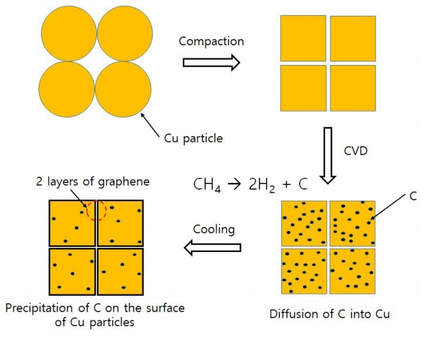
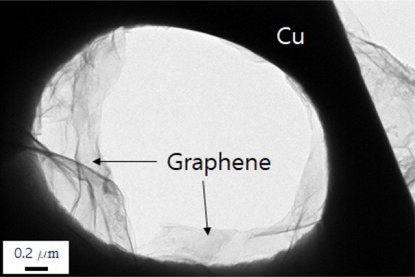
Figure 5 shows a schematic diagram of the synthesis of the 3DiGn-Cu composite [25]. At the initial stage of CVD, carbon diffuses relatively easily through the boundaries of the Cu particles, thereby reaching every part of the Cu disc; with the diffusion coefficient (D) of ~ 139 μm2/s at 1030 °C [29], ~ 6 ppm of carbon dissolved into the Cu particles at 1000 oC [30]. The diffusion of Cu among the Cu particles results in reduced volume and the growth of Cu particles due to the driving force to reduce the surface energy in the middle stage. At the last CVD stage, carbon precipitates out from neighboring Cu particles, resulting in the formation of graphene, mostly in two layers at grain boundaries during cooling. The graphene in the 3DiGn-Cu composites forms at Cu grain boundaries and thus is connected continuously in three dimensions throughout the Cu matrix. Figure 6 shows TEM images of the graphene on Cu. The grain above graphene was removed by electrolyte thinning and polishing with a Struers TenuPol-5 [25]. The graphene exhibited a good attachment to the underlying Cu matrix.
A Raman spectral analysis was performed and reported previously [25] for 3D graphene, which was prepared by etching Cu completely from the 3DiGn-Cu composite to leave only the 3D graphene as shown in Fig 7. Details regarding sample preparation and analytical procedures can be found elsewhere [25]. The Raman analysis showed that the intensity ratio of the 2D to G peaks was approximately 1, indicating that the 3D graphene had mostly 2 layers. In addition, the relative intensities of the D to G peaks (~ 0.22) reflect the high quality of the graphene with few defects [31-33].
To determine the TCs of the 3DiGn-Cu composites, we examined their thermal properties by measuring the thermal diffusivity using laser flash analysis and specific heats with differential scanning calorimetry analysis. To obtain a high TC by utilizing graphene in metal matrix composites, the graphene should be sufficiently aligned with the metal matrix [20]. Furthermore, high-quality graphene with minimized defects is also essential for graphene-metal matrix composites, as defects naturally act as phonon-scattering centers and thus degrade the TCs of graphenes and their composites [9,35].
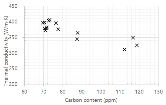
The carbon contents were measured using the ELTRA CS-2000 analyzer with a precision of ± 0.3 ppm. The density vs. carbon content of the 3DiGn-Cu composites is plotted in Fig. 8, and shows that the amount of carbon in the 3DiGn-Cu composites decreases with increasing density of the same composites. A parabolic fit to the density vs. carbon content data provided an R2 value of 0.99. The relationship of TCs to the amount of carbon in the 3DiGn-Cu composites is shown in Fig. 9. The figure shows that as the amount of carbon decreases, the TCs of the 3DiGn-Cu composite increase; however, the maximum TC of 406 ± 5 W/mK in the 3DiGn-Cu composite was obtained at a carbon content of ~ 73 ppm. A further decrease in the amount of carbon resulted in a decrease in TC, indicating that there is a threshold for the amount of carbon to obtain the maximum TC in 3DiGn-Cu composites.
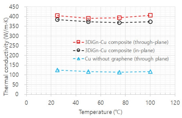
The thermal properties of the 3DiGn-Cu composite and Cu without graphene were measured between room temperature and 100 °C and are presented in Fig. 10. For comparison, the Cu-only sample was prepared by the same method used for the preparation of the 3DiGn-Cu composites, but without CH4 gas, during CVD. For the 3DiGn-Cu composite with a density of 8.16 g/cm3 and carbon content of ~ 73 ppm, enhanced TCs of 406 ± 5 W/mK and 385 ± 7 W/mK in the through- and in-plane directions, respectively, were obtained at room temperature. For in-plane TC, the temperature rise on the rear surface was measured at three different positions (5, 10, and 13 mm from the center of disc) and averaged. Therefore, the lower in-plane TC compared with the through-plane TC could be attributable to the increased number of defects as the measurement distance increased from 0.9 mm (through-plane) to 13 mm (in-plane). For comparison, the through-plane TC of Cu without graphene was measured as 125 ± 5 W/mK, which is almost thrice lower than that of the 3DiGn-Cu composite.
Many studies have indicated that the volume fraction of carbon, its spatial distribution, and carbon-matrix interphase properties affect the macroscopic TC of graphene-metal composites [35]. Therefore, it is reasonable to conclude that the spatial distribution of the three-dimensionally interconnected continuous graphene network throughout the Cu matrix must pro- vide effective pathways for thermal conduction in the 3DiGn-Cu composite, resulting in a relatively high TC. However, the mechanism involved in the thermal conduction of 3DiGn-Cu in relation to the radius of curvature for the 3DiGn, i.e., bent, anchored, and wrapped around Cu grains, is not known. Therefore, it is necessary to further investigate the TC of the 3DiGn-Cu composite in relation to the shape of graphene.
4. CONCLUSION
We demonstrated a three-dimensionally interconnected graphene-networked Cu (3DiGn-Cu) composite fabricated by a simple two-step process: compaction of Cu powder with 99% purity followed by CVD. The fabrication process and Raman analysis of the 3DiGn-Cu composite indicated the precipitation of carbon from neighboring Cu particles, which resulted in the formation of (typically) 2 layers of graphene at the Cu grain boundaries. Lastly, the enhanced through-/inplane TCs indicate that the three-dimensionally interconnected graphene network (3DiGn) in a Cu metal matrix provides effective pathways for thermal conduction. Therefore, even though the TC obtained herein is not as high as that recently reported, it is worth considering this new and easy fabrication method for 3DiGn-Cu composites and its possibilities for numerous applications. To achieve a sufficiently high TC in the 3DiGn-Cu composite comparable to the TC of graphene, our ongoing research will focus on not only fabricating 3DiGn but also on the shape and quality of graphene in the 3DiGn-Cu composite.