


1. Introduction
Boron Nitride Nanotubes (BNNTs) are one of the basic new nano materials being investigated by researchers in anticipation of industrial applications. Since the first paper on BNNT synthesis was published in 1995 [1], BNNT-related research has steadily increased [2]. BNNT is a combination of nitrogen and boron, and has the same hexagonal nanotube structure as CNT (Carbon Nanotubes). Because of their structural similarities the physical properties of BNNT are comparable to those of CNT. For example, BNNT mechanical properties, thermal conductivity, and thermal expansion characteristics are similar to those of CNT [3-6]. BNNT also has ceramic characteristics, so it has better high temperature safety and chemical resistance than CNT [7-9]. Given these many excellent physical characteristics, application research on BNNT is currently being conducted in various industries.
Various BNNT application studies are also being conducted in the energy industry, including for hydrogen storage. Hydrogen is well-known around the world as a clean fuel, and one of the candidates to replace current carbon-based fossil fuels. To utilize hydrogen, hydrogen storage technologies must be developed and implemented on an industrial scale. Recent research has been conducted on nanostructured materials which can store hydrogen via physical adsorption, including CNT and BNNT, which have a highly porous structure, low mass density, and very large specific surface area [10-14]. It has been reported that hydrogen storage capacity due to physical adsorption is increased by the presence of defect points in the nanostructures or with more open edges, i.e., less crystalline nanostructures [15].
Ion beam irradiation is a technique that can finely change a material's surface's physical, chemical, or mechanical properties at the atomic level. At the surface, the beam energy is converted to kinetic energy, causing a chain collision of atoms within the area where the beam is focused. Atoms on the sample surface are removed by evaporation or elastic collisions or rearranged due to melting or inelastic collisions. Ion beam irradiation is mainly used as a surface engineering technology in areas of micro/nano scale.
In this study, BNNT was synthesized using the RF Plasma method, and nitrogen ions were irradiated on the surface of the BNNT, and structural changes in the BNNT were investigated according to the ion beam energy.
2. Experiments
2.1 BNNT synthesis and specimen preparation
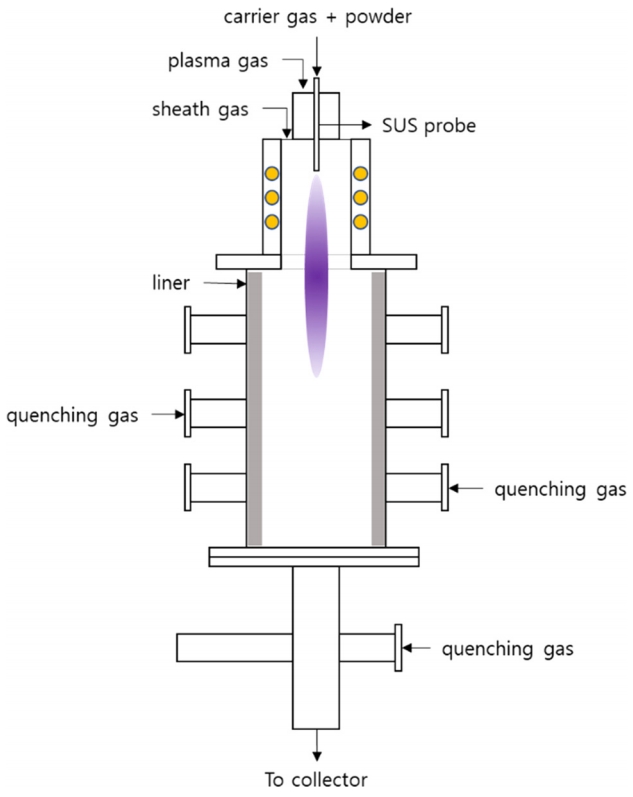
The BNNT for this study was synthesized using a 60 kW RF plasma torch system. A 70 nm sized boron nitride (h-BN) powder was used as the raw material. This plasma torch BNNT synthesis method was introduced by K. S. Kim. This synthesis method uses the Ar/H2/N2 gas discharge. The BNNT is formed by high temperature plasma of h-BN powder, and synthesized BNNT is collected in the collection device [16]. Fig 1 shows a schematic diagram of the plasma torch used for the synthesis of BNNT. Hydrogen was added during the synthesis process to improve the BNNT manufacturing reaction. The BNNT synthesis conditions for this study are shown in Table 1. The addition of hydrogen to improve the BNNT manufacturing reaction is characteristic of this synthesis method, and makes it possible to synthesize highly crystalline BNNT with a very small diameter. In the synthesis, un-melted h-BN particles and amorphous boron are produced as impurities. The synthesized BNNT mixture was then heated at 650 °C for 6 hours to change the amorphous boron in the mixture to B2O3 and then for dispersion was subjected to ultrasonic waves in methanol for 30 minutes. A membrane filter was then used to separate the B2O3 and BNNT compounds dissolved in the methanol dispersion solution. The refined BNNT compounds were then mixed at a rate of 0.002 g per 100 ml of ethanol using ultrasonic waves for 30 minutes. Two to three drops of the dispersion solution were dropped into a carbon coated TEM grid (Pure Carbon, 200 mesh, Cu) to produce specimens for ion beam irradiation and microstructure analysis.
2.2 Ion beam irradiation
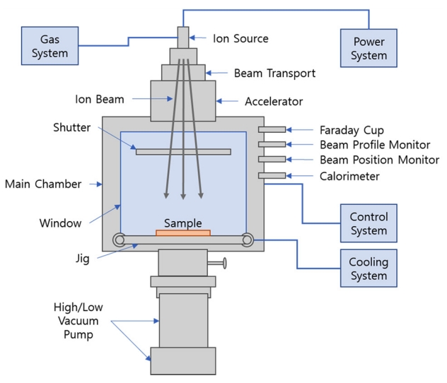
Nitrogen (N2) gas was used for the ion beam irradiation. The ion beam was irradiated on the surface of the BNNT specimen using an ion injection device (Neopion Co., Ltd., Korea) as shown in Fig 2. The ion beam irradiation was conducted in a vacuum at 3 × 10⁻⁵ torr, with an ion irradiation (dose) ranging from 1 × 10³ to 1 × 10¹⁷ ions/cm2 at applied ion beam irradiation energies of 40 keV, and 50 keV. The ion irradiation dose was calculated by establishing the area of the specimen being examined, the amount of current, and the time duration.
The ion injection device introduces the gas into the vacuum tube, forms a plasma, and then accelerates the cation in the plasma by applying high voltage to the surface of the material, allowing it to crash and be injected into the surface of the material.
2.3 Characteristics analysis
The microstructural changes in the BNNT following ion irradiation were confirmed using HR-TEM (JEM-2010, JEOL, Japan). The vibration characteristics and lattice vibration characteristics of the BN nanostructures produced by ion irradiation were identified using Raman spectrometry (LabRAM HR, HORIBA, Japan) and FT-IR spectrometry (Nicole iS50, Thermo Fisher Scientific Inc. USA), respectively.
3. Results and Discussion
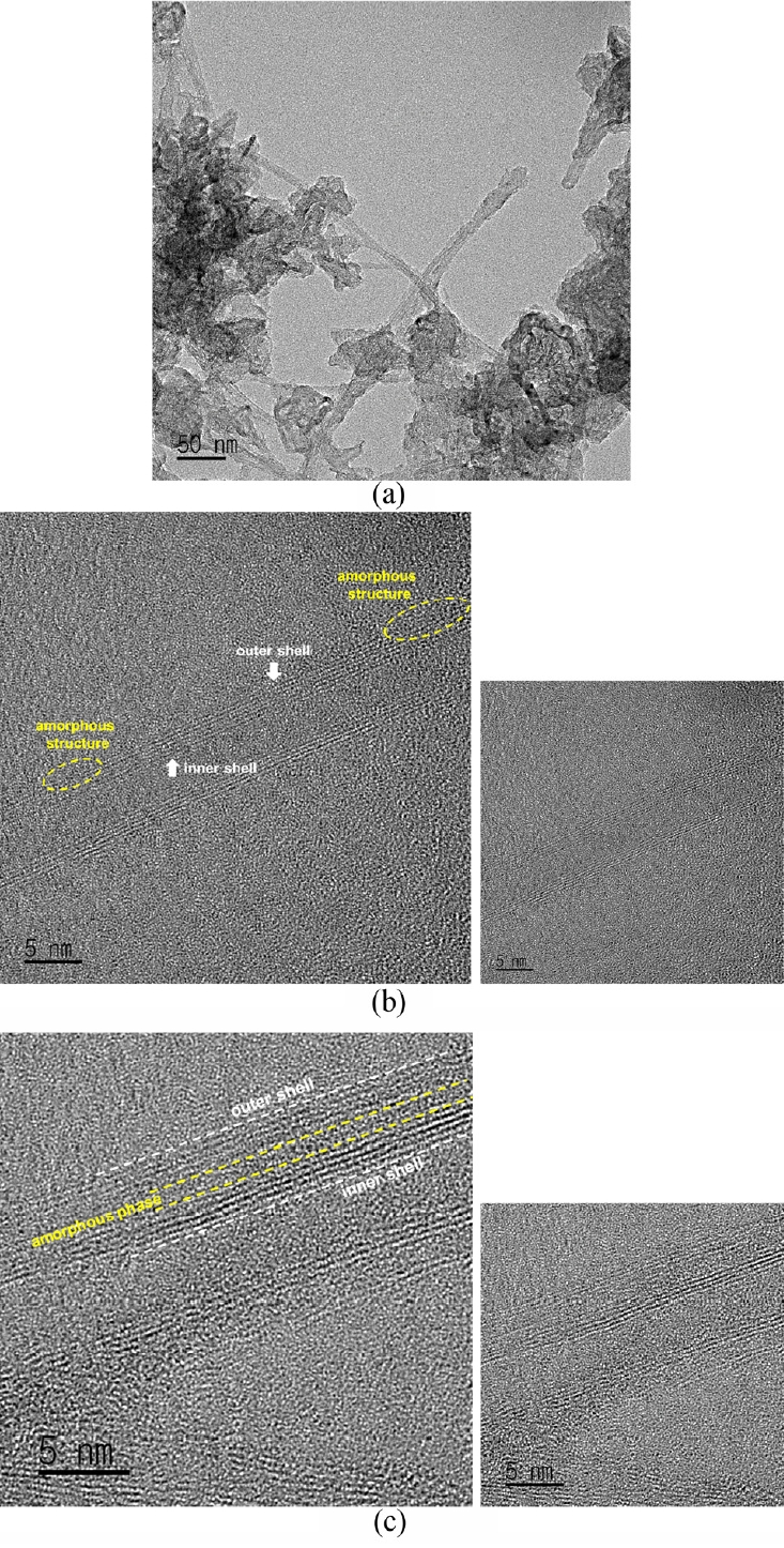
Fig 3 shows a TEM image of the microstructure of the synthesized BNNT, and the BNNT following ion beam irradiation. Fig 3 (a) shows a TEM image of BNNT which has undergone a post-synthesis refining process, and a sample of BNNTs grouped together which has a length of hundreds of nm or more. (b) and (c) in Fig 3 are TEM images of the synthesized BNNT after irradiation with a N2+ ion beam dose of 1 × 10¹⁵ ions/cm2 at a beam energy of 40 keV (b) and 50 keV (c).
The synthesized BNNT is a multi-walled BNNT with a wall thickness of about 5 nm. As the ion beam dose is increased, the BNNT’s tube structure becomes more and more disordered, and finally changes into an amorphous structure [17].
At an ion beam energy of 40 keV, the outermost tube shell of the BNNT was partially broken and changed into an amorphous structure. At an ion beam energy of 50 keV, the tube shell in the middle of the multi-walls became disordered, forming a continuous amorphous layer. This change can be attributed to the difference in ion penetration depth due to the higher ion beam energy. This microstructural change was not seen when the irradiation beam was less than 1 × 10¹⁵ ions/cm2 at each ion beam energy.
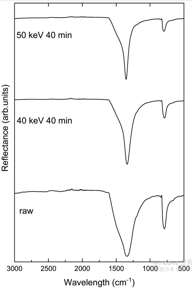
Fig 4 shows the variation in Raman spectrum following ion beam irradiation. The Raman spectrum of the BNNT was similar to the Raman spectrum of h-BN. All BN nanostructures represent only one E2g mode, which is a Raman active mode, in the wavelength range of 1,000 to 1,500 cm-1. The E2g mode of BN is a mode derived from the in-plane atomic arrangement, in which the B and N atoms are against each other [18]. The peak of the synthesized BNNT was located at 1370 cm-1. The peak of the BNNT irradiated at 40 keV with N2+ ions 1 × 10¹⁵ ions/cm2 was located at 1368 cm-1, and at 1365 cm-1 for ion beam irradiation at 50 keV. The E2g mode of all BN nanostructures is transferred to a lower frequency region than the BN in bulk form, which is reported to be due to reduced crystallinity [15,19]. A. L. M. Reddy et al. reported a 0.2~0.3 wt% improvement in hydrogen storage capacity by physical adsorption, although the peak shifted to 4~5 cm-1 lower frequencies with decreasing crystallinity. They also reported that this improvement in hydrogen storage capacity may be due to the presence of more defect sites and many open edged layers on the BNNT outer surface [15].
In this study, the crystalline structure of BNNT was reduced due to the generation and increase of amorphous structure by ion beam irradiation, which can be seen in the results as peaks shifting to lower frequency. These results suggest that the microstructural deformation produced by ion beam irradiation can be useful for improving hydrogen storage capacity.
Fig 5 shows the FT-IR spectrum of the synthesized BNNT, and the ion beam irradiated BNNT. The FT-IR spectrum provides additional information about the lattice vibrations of the BN nanostructures. The FT-IR spectrum of the synthesized BNNT is located near two strong characteristic peaks of 800 cm-1 and 1360 cm-1. That of the ion beam irradiated BNNT is similar to the synthesized BNNT. The characteristic peaks were not changed by ion irradiation. The peak of the 800 cm-1 band represents the A2u mode, which corresponds to the BN vibration perpendicular to the BNNT tube axis, and the peak of the 1360 cm-1 band represents the E1u mode, which is due to the BN vibration parallel to the tube axis [15,20]. The peak produced by the A2u mode of the BN nanostructure, i.e., the BN vibration perpendicular to the tube axis, was shifted to a lower frequency compared to the BN bulk form [15,21]. This shift in frequency is due to the buckled structure in BNNTs.
4. Conclusions
Multi-walled BNNT with a wall thickness of 5 nm was synthesized using a plasma torch system. The synthesized BNNT was irradiated with N2+ ions, and part of the tube shell was transformed into an amorphous structure. At an ion beam energy of 50 keV, a continuous amorphous layer was formed in the middle of the multiple walls. The reduction in the crystalline structure of the BNNT by the formation of amorphous structure was confirmed by Raman spectra. The reduction in nanocrystalline structure by ion injection will advance the application of BNNT for hydrogen storage by physical adsorption.