


1. Introduction
Lithium-ion batteries (LIBs) are essential power sources in a wide range of products in our modern society. Portable devices ranging from mobile phones to laptops, from electric vehicles (EV) to large-scale energy storage systems (ESS) are powered by LIBs [1-3]. Considerable research has been devoted to efforts to enhance their energy density, power density, life span, and total capacity. Among them, various attempts to improve the performance of the separator, which is an essential component of a robust LIB, have been made by numerous researchers. These separators provide chemical stability and mechanical strength, but they are typically too soft and will melt at high temperatures [4,5]. The difference in the polarities of the separator and electrolyte surface also has a negative impact on LIBs [6,7].
Recently, several efforts have attempted to address the weaknesses of the standard separator. Micro-nano particles prepared as inert ceramic oxides (Al2O3, SiO2, and TiO2) have been coated on the separator to increase ionic conductivity, and reduce the safety problems caused by internal electrical short circuits [8-11]. The ceramic-coated separator provides micropore channels for lithium-ion migration, acts as a wall between the anode and the cathode, and prevents electrical shorts from the anode [4,5]. For these reasons, ceramic-coated separators are currently used in all EV batteries. Polyimide (PI) has also been used as a separator because of its thermal stability, high tensile strength, and excellent electrolyte wettability [12-14]. However, it is rarely used in applications, because of the high cost and complex manufacturing process of PI membranes.
In this study, we examined the differences of commercial polypropylene (PP), ceramic (Boehmite) coated PP (C-PP), and polyimide (PI) separators from an electrochemical perspective. For the battery model, the half-cell using lithium nickel manganese cobalt oxides (NMC), which is the most used in the current industry, and the full-cell using graphite as the opposite electrode were adopted [15]. We conducted rate capability tests at rates from 0.1 to 5 C, focusing on the differences in each C rate section. Also, a high C rate cycle stability test was conducted to determine which separator membrane could maintain good performance, even at fast charge and discharge rates, which is essential to meet the demand for fast charging in mobile devices and electric vehicles.
In addition, electrochemical impedance spectroscopy (EIS) tests were carried out for each separator. EIS is a powerful tool for determining charge-transfer resistance and solid electrolyte interphase (SEI) layer resistance which has high resistance similar with nonconductor [16]. After the cycle tests, we also disassembled the cell and checked both sides of each separator, and the surface of the NMC electrode. Finally, we tested the three separators in an NMC//graphite full-cell system to study each separatorŌĆÖs performance from a commercial perspective.
2. Experimental Procedure
2.1 Material Information
The polypropylene (PP) separator was purchased from Celgard 2400. The ceramic-coated polypropylene (C-PP) was purchased from Everener Battery Solution (Korea). Boehmite was coated to a 4 um thickness on the 12 um thick PP separator. The porous polyimide (PI) separator was purchased from TOK (Japan). The porosity of the PI separator was 70 % and thickness was 20 um. As the electrolyte, 1 M LiPF6 in ethylene carbonate (EC):dimethyl carbonate (DMC) (1:1 wt%) products from the company ENCHEM (Korea) were used. The lithium metal chip was a 16 ╬” product of NEBA (Korea). NMC is a product of LGCHEM with a nickel, manganese, cobalt ratio of (8:1:1). The 2032 coin-cell parts were purchased from Welcos corp. (Korea).
2.2 Cell assembly
The NMC electrode was prepared by the slurry doctor blade coating method. The NMC power was mixed with a carbon additive (Carbon Black, Super-C) and polyacrylic acid (PAA) binder at an 8:1:1 ratio (wt%) in series with the proper amount of DI water as a solvent. The slurry was coated on 20 um thickness aluminum foil by doctor blade. The material loading mass was set as 2.5 mg cm-2. The graphite anode was made by Alfa Aesar using the above doctor blade procedure and 20 um thick copper foil. The sample 2032 coin type cells were assembled using PP, C-PP, and PI as the separators, the NMC electrode as a working electrode, lithium metal as a counter, and a reference electrode in a glove box filled with Argon gas. The ceramic coated side was aligned to face the lithium metal. In the NMC//graphite full cell assembly, lithium metal was replaced by the graphite electrode. 1 M LiPF6 in EC:DEC (1:1) and EC:DMC (1:1) were used as electrolytes.
2.3 Characterization and analysis
The surface morphologies of the PP, C-PP, and PI separators were visualized by field emission scanning electron microscope (SEM, Jeol, JSM-7500F). The cell performance was evaluated using a Wonatech Cycler System (Wonatech, WBCS3000). The potential window was set at 2.8~4.2 V. The cycle testing was performed using a galvanostatic charge-discharge analysis with a 5 C rate. The rate capability test was performed at 0.1, 0.2, 0.5, 1.0, 2.0, 5.0, 0.1 C rate in sequence (1 C = 150 mAh gNMC-1). In the full cell cycle test, the first 5 cycles were tested at the 0.1 C rate for electrode activation, and after that, 200 cycles were set with the 1 C rate. EIS analysis was conducted using a Biologic potentiostat (Biologic, VMP-3). We used a 105~10-1 Hz scale and EIS fitting was performed using the EC-Lab software Z-fit program.
After the cycle tests, the coin cells were carefully disassembled in a glove box to extract the shaped separator. The obtained separators were rinsed in DMC based on their used electrolyte composition, in a glove box. After complete drying, SEM analysis was carried out to determine the differences in the morphology of each side. When measured at a high voltage, the separator structure burns. So the acceleration voltage of the SEM electron beam was set to 3 kV.
3. Results and Discussion
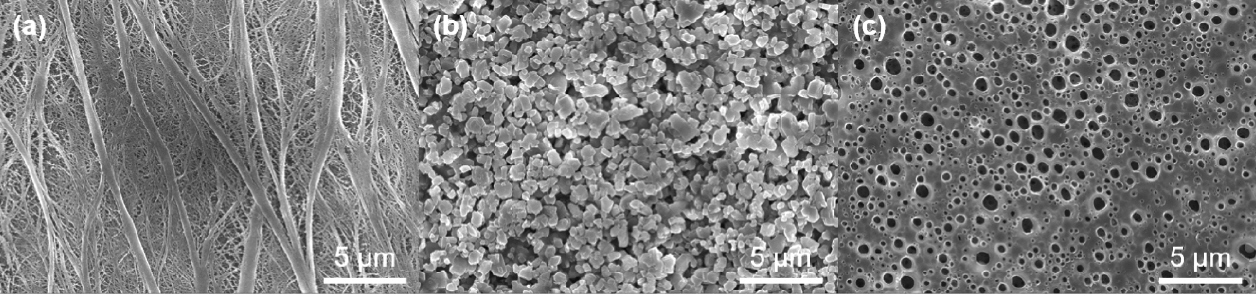
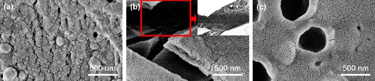
First, we attempted to determine the surface structure of each separator by SEM analysis. Fig 1 shows the surface SEM image of the PP separator, which has a fiber structure with very small porosity. Fig 1(b) shows the surface of the C-PP separator exhibiting the porous ceramic coating layer composed of 1~10 um boehmite particles. This layer prevents the shrinkage problem that occurs at high temperatures of 100 to 200 ┬░C [17]. The PI separator has a porous structure like a sponge, with 1~10 um sized pores, as shown in Fig 1(c). The high porosity of the PI separator allows the electrolyte to transfer easily, and this is the main way its reduces internal resistance (RS).
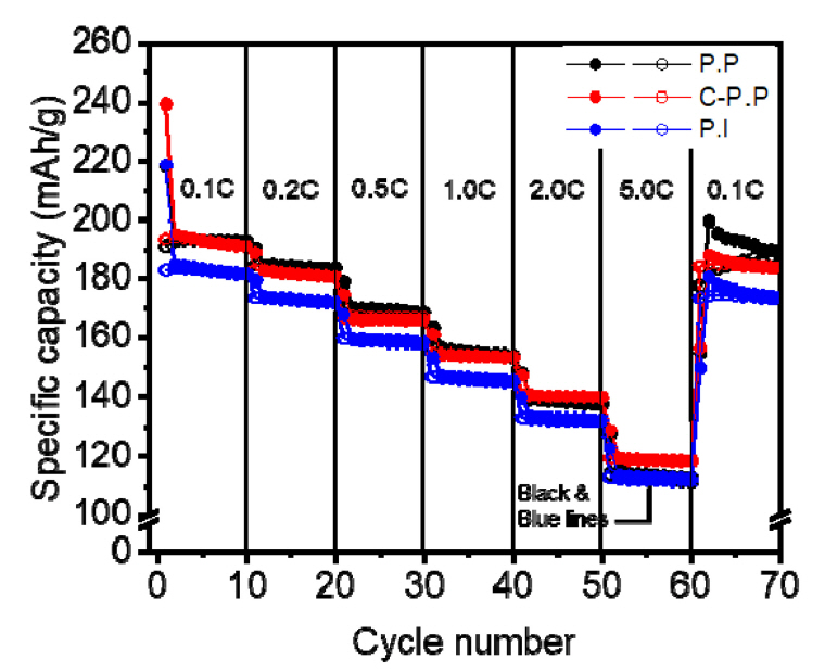
Electrochemical tests were carried out to examine the difference in battery performance with the three separators. As shown in Fig 2, the discharge capacities of the three separators were 192 mAh g-1, 190 mAh g-1, 181 mAh g-1. There was no significant difference between the PP cell and the C-PP cell in the first few cycles. As the cycles increased, the capacity retention characteristics and stability in the C-PP cell were excellent. Even at a high current density at the 5 C rate, the capacity of the C-PP cell was the highest, 112 mAh g-1. Notably, the PP cell had a sharp drop in capacity when compared to the 2 C rate, which was the previous current density.
For the next 10 cycles at the 0.1 C rate, the C-PP cell showed the best cycle stability performance. The capacity of the C-PP cell decreased from 188 mAh g-1 to 183 mAh g-1, only a 2.3% drop. This fading was only half that of the PP cell (200 mAh g-1 to 190 mAh g-1, almost a 5% decrease) and the PI cell (180 mAh g-1 to 174 mAh g-1, almost 3.6%). These results suggest that the ceramic layer in the C-PP separator influences the stabilization of the lithium ions and intermediate ions [18]. By adding the ceramic coated layer to the separator, interfacial impedance was reduced and lithiumion migration was promoted across the coating layer [17]. Also, ceramic layers can prevent electrolyte leakage during repeated cycles [19]. The PI separator has many micro-pores, and not only lithium-ion but other intermediates can also migrate through these pores. This phenomenon is the main reason for the capacity fading observed with PI cells.
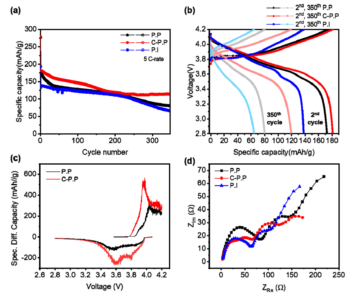
Based on these results, we established the cycle stability performance of each of the three cells at the 5 C rate, as shown in Fig 3. Since the difference in capacity and stability was large at the 5 C rate, cycle measurements were performed at the corresponding current density. As shown in Fig 3(a), the irreversible capacity and initial capacity in the PP cell and the C-PP cell were similar at 174 mAh g-1 and 181 mAh g-1, respectively, and only the PI cell showed a relatively low capacity of 138 mAh g-1. However, after 200 cycles, the C-PP cell maintained a capacity of 115 mAh g-1. The PP cell continued to decrease to a capacity of 80 mAh g-1 and the PI cell declined to 64 mAh g-1.
Fig 3(b) shows the charge-discharge voltages of the three cells vs. Li/Li+. The capacitive slope of the C-PP cell was higher than the other two cells between 3.4 V and 4.0 V. And the PI cell hardly showed any capacitive slope in the section of the 350th charge-discharge graph.
To examine this result more precisely, we analyzed the differential capacity vs. cell voltage graph for each cell after the 350th cycle, as shown in Fig 3(c). The y value of this graph represents the plateau of each graph, and the higher the value, the longer the plateau region. In the C-PP cell, a redox peak exists near 4.0 V and 4.15 V. Each peak represents the phase transition of NMC from monoclinic (M) to hexagonal (H2) and then from hexagonal (H2) to hexagonal (H3). In the oxidation peak, a large sharp peak was observed near 3.6 V. This peak can be explained as the phase transition of the NMC from a hexagonal to a monoclinic (H1 ŌåÆ M) lattice [20]. The main reason for capacity fading near the discharge region is rapid volume contraction during the structural transformation from H2 to H3 phase [21]. Using the C-PP separator, the peaks were less polarized, less shifted, and maintained the capacity reaction.
To better understand the results of the cycle test, we used EIS analysis. As shown in Fig 3(d), the resistance of the high-frequency region is related to the SEI layer of the electrode (RSEI) [22]. In low-frequency region, the resistance represents the charge-transfer resistance of the two electrode-electrolyte interfaces (RCT) [22]. By using the Z-fit program with the EIS model of the NMC half-cell, we calculated the resistances of the solution, SEI layer, and charge-transfer for each cell, as listed in Table 1.
In Fig 3(d), the resistance of the C-PP cellŌĆÖs SEI layer was determined to be the lowest of the three samples. The result indicates the intermediates of several phase of NMC were less than other separators [23]. The ceramic inert oxides coated on the surface of the polymer separator led to an increase in ionic conductivity [5], and thatŌĆÖs why the C-PP separator had the lowest impedance value. Overall, despite the extremely fast 5C rate condition, our experiments demonstrated remarkable results in capacity stability, compared to previous papers using ceramic-coated separators [8,24-26].
3.1 Cell disassembly after cycle tests
After the cycle testing at the 5 C rate, we disassembled the cells and analyzed the separators and electrode surfaces. Part of the PP separator structure was broken, and the opaque white tissue was changed to a thin translucent tissue. More than 90% of the PP separator that was directly facing the electrode became a thin translucent structure. However, in the C-PP cell, the separator retained its original structure. In the PI cell, there was a dark green region directly facing the electrolyte. The edge part was pressed by the gasket when the coin cell was assembled and did not contact the electrolyte. But after perfectly drying the solvent, that separator returned to its original yellow color. Because the PI separator had 70% porosity, the structure was easily torn. After sufficient drying, we peeled off the separator and carried out the SEM analysis.
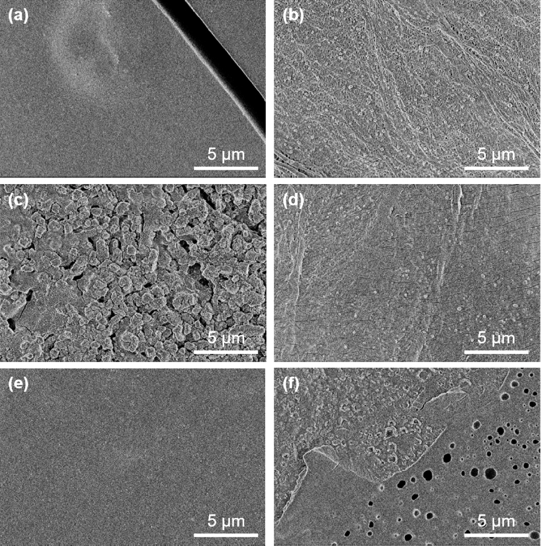
In Fig 4, the SEM images of each separator are shown. All of the left column images are the Li facing side, and the right column is the NMC electrode facing side. The separator tissue on the lithium-facing side was almost fully covered with some type of material. However, it maintained half of the original structure of separators facing NMC electrodes. Most of the pores in the PI separator were blocked by the layer, which means that the internal structure was also affected. That is, the pore volume of the fiber-like PP structure was decreased by the stacking of some intermediate layer on the fiber structure.
Lithium-ion diffusion through a separator is a significant issue in battery performance. If transport paths are blocked by the SSEI layer, then ionic conductivity will decrease, and that can cause some serious problems for long-term cycling. Moreover, if this phenomenon becomes severe, the separator pores will be blocked by the SSEI layer, as we see in Fig 4(a), (e).
As shown in Fig 4(c), the rough ceramic layer was covered with the SSEI layer, and the porous sponge-like structure was blocked by the SSEI layer in Fig 4(e). However, as shown in Fig 5(b), only a thin layer was formed on the surface of the C-PP separator, and as observed through cracks on this surface, the original structure of the internal PP fiber was retained. In addition, the surface of the PP (Fig 5(a)) and PI (Fig 5(c)) separators had a thick SSEI layer. Therefore, the use of a C-PP separator seems to be a good strategy to prevent the pores of the separator from being blocked by the SSEI layer, as indicated by our electrochemical analysis.
We also examined the NMC electrode surface using SEM and EDS analyses. Observing the surfaces of each electrode, we found the overall morphology to be similar, and there were no issues such as coating problems. However, it was noted that nickel and manganese elution of the NMC occurred, causing a decrease in capacity when the battery continued to be charged and discharged. We measured the EDS of the electrode surface to confirm the ratio of surface elements [27]. As summarized in Table 2, the atomic ratio of each element was compared based on the relatively stable cobalt. The manganese ratio of the electrode using the PP separator was found to be lower than that of the other two separators, and the electrode using the PI separator had the lowest ratio of nickel. On the other hand, the electrode using C-PP had a high ratio of both nickel and manganese, which can be explained since the elution of nickel and manganese was suppressed by the C-PP separator.
3.2 Full-cell application
We also conducted a NMC//Graphite full-cell cycle test to compare the three separatorsŌĆÖ performance. As shown in Fig 6(a), in the first 5 cycles, the C rate was set to 0.1C to stabilize the NMC electrode and the graphite electrode. After the 0.1 C rate cycle, we set a 1.0 C rate for 200 cycles, for a charge-discharge analysis. The C-PP and PP cells exhibited the best capacity of 115 mAh g-1 among the three, and maintained 70% capacity after 200 cycles.
However, the PI cell was stable but showed low capacity. To determine the reason for the differences among the separators, we conducted an EIS analysis after the cycle stability test. In Fig 6(b), the Nyquist plots of each of the three separator cells are illustrated. In the high frequency region, the semi-circle of C-PP was smaller than the other graphs. At this point, we used the Z-fit program with the full-cell model. This model is composed of solution resistance, SEI layer resistance, anode resistance, and cathode resistance. The results are organized in Table 3. We observed that the SEI resistance of the C-PP cell was lowest for the three sets. The structure of the C-PP separator was maintained by the ceramic layer, and that affected the cycle performance.
4. Conclusion
In this study, we report the differences of PP, C-PP and PI separator surfaces after cycle testing. The electrochemical properties of these separators were also observed in half-cell and full-cell tests. In the rate capability test, the C-PP separator showed stable and high capacity characteristics at a high 5 C rate. Because of the ceramic layer on the PP membrane, lithium-ion migration was stabilized and the phase transition of NMC was well controlled. Also, a less resistive solid electrolyte interphase was the critical factor in the C-PP separator performance.
To examine the surface of each separator, we disassembled the cycled cells and observed the surfaces of both sides of the separator and electrode surface. Normal PP and PI separators were blocked by electrolyte intermediates, known as the SSEI layer, and this phenomenon made it difficult for lithium-ions to effectively migrate by reducing the pore size of each separator. However, with the C-PP, the coated ceramic layer worked as a barrier, so the internal fiber structure was maintained, and this played a significant role in ionic conductivity. These ceramic layers can effectively limit SSEI layer formation on the PP separator from, reducing the effect of the stacked intermediates on the separator structure and pores. In addition, based on the EDS results of the NMC electrode, the C-PP separator helped prevent manganese and nickel element elution to the anode through the electrolyte and separator. Finally, the results of the NMC//Graphite full-cell confirmed that cycle stability was excellent when the C-PP separator was used. Our work can provide guidelines for the life management of EV batteries and separator development issues.
As shown in Fig 3(d), the resistance of the C-PP cellŌĆÖs SEI layer was the lowest among the three samples. The result suggests the intermediates of several phase of NMC were less than the other separators [23]. Coating the surface of polymer separators with the inert ceramic oxides leads to an increase in ionic conductivity [5], and thatŌĆÖs why the C-PP separatorŌĆÖs had the lowest impedance value. Overall, despite the extremely fast 5C rate condition, our experiments achieved remarkable capacity stability compared to previous papers using ceramic-coated separators [8,24-26].