


1. INTRODUCTION
As the crude oil mining environment becomes worse, the market demand for crude oil extraction in sour environments is increasing. Especially in the Middle East, which is the main production area for crude oil, there is a high demand for normalized heat treated steels for sour service applications. The normalized steels have excellent uniformity of strength and high stability because of the normalizing heat treatment, and as a result, are well suited for sour service applications.
Hydrogen can be trapped in steel in areas of high stress intensity. The two most common areas of high stress intensity are un-modified non-metallic inclusions [1,2] such as MnS, silicates or oxides [2-5], and the interfaces resulting from microstructural banding that can occur during steel processing. Microstructural banding, which has been observed in finished products, occurs in the slab-alloy centerline segregation that develops during the solidification of steel. Normalized steels used in pressure vessels for sour service applications are highly susceptible to hydrogen induced cracking (HIC) due to the significant frequency or size of non-metallic inclusions, or undesirable volume fractions of banded microstructures [1,6-15] or, in some cases, both. Among the possible microstructures that could improve the HIC performance of steels, the polygonal ferrite/pearlite microstructure is the least desirable. In contrast, polygonal ferrite/bainite and, in particular, a low carbon bainite (acicular ferrite) microstructure has exhibited enhanced HIC resistance in line pipe steels produced using the thermo-mechanical control process (TMCP) [10,16-21].
After being rolled down, TMCP alloys undergo direct water cooling to temperatures in the 400-600 °C range. During this cooling process, austenite mainly transforms into bainite. As a result, TMCP steels are less likely to present a banded ferrite/pearlite structure, and are highly resistant to HIC. However, variations in microstructure and mechanical properties can occur in TMCP steels depending on location (such as the head, tail, corner, or center) due to the unevenness of water cooling after rolling. Normalized pressure vessel steels, on the other hand, commonly exhibit uniform mechanical properties. Since the safety of pressure vessels is very important, developing normalized steels with strong HIC resistance has been a priority for researchers. However, there is a lack of studies which combine the advantages of normalized steel (mechanical homogeneity) and the advantages of TMCP steel (non-banded structure by bainitic transformation).
In the early days, the normalized heat treated steels for sour service application were manufactured using an alloy design that contained five key elements, C, Mn, Si, P, and S. Studies have been carried out to obtain better HIC characteristics with these compositions, and a more advanced alloy design containing Ni+Cu has been suggested. Previous studies have reported that nickel and copper were efficient at preventing the propagation of HIC [22]. However, even though the addition of Ni+Cu has improved HIC characteristics, there was only a partial improvement in corrosion resistance.
On the other hand, molybdenum is an element that promotes bainite transformation because of its high hardenability. Molybdenum has been demonstrated to improve the sulfide stress cracking resistance of quenched and tempered steels, and resistance to H2S in high-sulfur microalloyed steels in as-rolled conditions [23-25]. Therefore, it can be expected that the addition of molybdenum may lead to a reduction of the ferrite/pearlite banded structure, which is detrimental to HIC properties, by promoting a bainite transformation, which is an advantage of TMCP steels, and in normalized heat-treated steels.
In this study, normalized pressure vessel steels with a molybdenum-added alloy design, hereafter referred to as the MA (Mo) alloy, was compared with an alternative alloy design, which contained copper and nickel, hereafter referred to as the MF (Ni+Cu) alloy. Each microstructure that resulted from the alloy/process design was evaluated along with its ultimate effect on HIC susceptibility.
2. EXPERIMENTAL PROCEDURE
The chemical compositions and abbreviations of the steels studied in the paper are listed in Table 1, and are within the typical range of chemical compositions of normalized pressure vessel steels for sour service applications. The structure and properties of an alloy that contained the deliberate amount of 0.10% molybdenum (MA (Mo) steel) was compared to a molybdenum-free alloy that contained nickel and copper instead (MF (Ni+Cu) steel).
The TM0284-2011 NACE standard test method was applied to measure the HIC susceptibility of the two steels. The specimens were immersed in a low-pH solution A for 96 h, as per the TM0177–2005 NACE standard method. The crack length and thickness ratios (CLR and CTR, respectively), which are HIC performance parameters, were measured according to the TM0284-2011 NACE standard. The performances of the MF (Ni+Cu) and MA (Mo) steels were compared by subjecting them to 92 HIC tests, and each HIC test was performed in triplicate. The steels were normalized heat treated, and the steel coupons were subjected to simulated post weld heat treatment (SPWHT) before the HIC test specimens were prepared. The SPWHT temperature was maintained at 600-620 °C for 60-180 min. The thickness of the HIC test specimens in this study ranged from 8 to 30 mm. Microstructural investigations were performed using scanning electron microscopy (SEM, JEOL JSM-7000F) and electron backscattered diffraction (EBSD).
3. RESULTS AND DISCUSSION
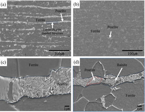
Figures 1 (a) and (b) illustrate the microstructure of the normalized heat-treated steel with and without added molybdenum, respectively. When molybdenum was added to the steel (MA (Mo) steel), ferrite/pearlite band structures formed and the thickness of the pearlite layer was measured to be approximately 6 μm. On the other hand, the volume fraction of the ferrite/pearlite band structure of the MA (Mo) steel was lower than that of the MF (Ni+Cu) steel, and the thickness of the pearlite layer was reduced to approximately 1.5 μm.
The volume fractions of microstructural constituents such as ferrite, pearlite, and bainite were measured using an image analyzer, and the results are reported in Table 2. The volume fractions of ferrite, and pearlite, and bainite of the MF (Ni+Cu) steel were 83, and 16, and less than 1% respectively, while those of the MA (Mo) steel were 87, 9, and 4%, respectively. Moreover, the average grain sizes of the MF (Ni+Cu) and MA (Mo) steels were similar: 6.2 and 6.6 μm, respectively. Figure 1 (c) confirms that lamellar structure pearlite was easily detected in the MF (Ni+Cu) steel. On the other hand, as can be seen in Fig 1 (d) , the austenite to bainite transformation was promoted by the addition of molybdenum, and caused the amount of banded ferrite/pearlite structure to decrease. Figure 1 and Table 2 show that molybdenum addition to the normalized steel effectively reduced the volume fraction of ferrite/pearlite banded structure, as bainite transformation occurred in the pearlite. Molybdenum addition also reduced the thickness of the pearlite and thereby imparted discontinuity to the ferrite/pearlite banded structure. Pearlite has a lamellar structure that is a more vulnerable microstructure for crack propagation [13,22].
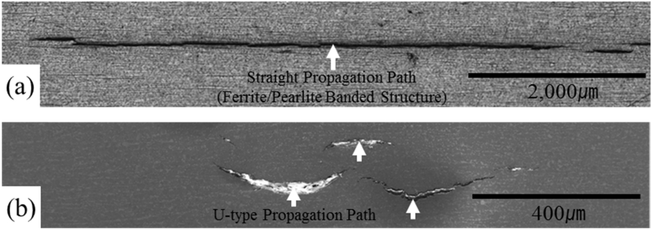
Figures 2 (a) and (b) present the macroscopic shape of the propagation of HIC depending on the presence or absence of molybdenum in the analyzed steels. The HIC of the MF (Ni+Cu) steel extended straight along the banded ferrite/pearlite structure [13,22]. However, the propagation tendency of HIC changed to a “U” shape and its length decreased in the MA (Mo) alloy. Considering this in relation to the results in Fig 1 and Table 2, the addition of molybdenum reduced the thickness of the pearlite and the continuity of the pearlite was lost. This discontinuity in the ferrite/pearlite banded structure seemed to affect the propagation behavior of HIC. In other words, the lamellar structure became a crack path, and crack propagation tended to go straight with less resistance in the MF (Ni+Cu) steel. However, in the MA (Mo) steel, discontinuity was formed in the ferrite/pearlite banded structure which increased the resistance to HIC propagation, and the propagation pattern changed into a “U” shape. This implies that bainite, presenting as randomly oriented microstructures, resisted HIC propagation much more effectively than the lamellar pearlite or ferrite/pearlite banded structures.
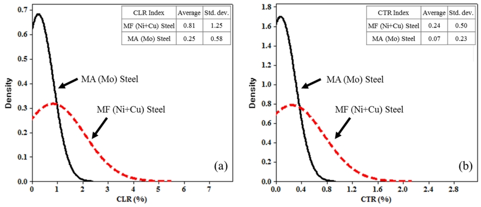
Figures 3 (a) and (b) depict the results of the TM0284-2011 NACE standard test. The CLR and CTR indices of the normalized MF (Ni+Cu) steel (indicated by the dashed red lines) were 0.81 and 0.24%, respectively. Meanwhile, the CLR and CTR indices of the normalized MA (Mo) steel (indicated by the black lines) decreased to 0.25 and 0.07%, respectively. From the normal distribution curves, it can be seen that the distributions of CLR and CTR came close to zero. This implies that less HIC initiation occurred or the size of the HIC decreased. In addition, the CLR and CTR distributions became narrower when molybdenum was added to the steel, which indicates that the crack size was uniform even when HIC occurred.
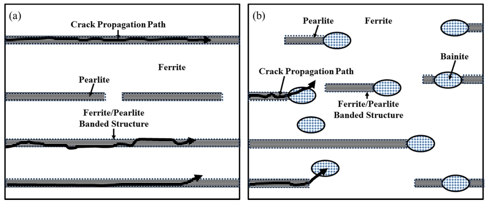
Figure 4 illustrates a schematic diagram of the effect of molybdenum addition on crack propagation. For the MF (Ni+Cu) normalized steel (Fig 4 (a) ), the HIC propagated straight along the banded ferrite/pearlite or lamellar pearlite structures, and exhibited a straight and long path length [13,22]. For the MA (Mo) normalized steel (Fig 4 (b) ), however, bainite exhibiting a random structure interfered with the propagation of HIC, which resulted in the “U” shaped short path length.
To analyze the relationship between HIC characteristics and microstructure in more detail, the area of the crack tip was carefully investigated using SEM, EBSD, and hardness measurements.
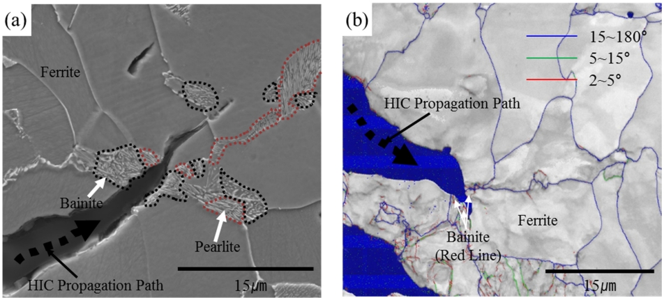
From the SEM image in Fig 5 (a) it can be seen that HIC propagated through ferrite and bainite, and then stopped. Bainite is a structure that occurs at a rapid cooling rate or in high hardenability alloy compositions [26]. To identify the microstructure at the end of the HIC propagation, EBSD analysis was performed, as presented in Fig 5 (b). It has been reported that bainite can be identified by measuring the kernel average misorientation (KAM) using EBSD. It exhibited a low KAM value, which ranged from 0.7 to 5° [27]. The red line in Fig 5 indicates a low angle boundary featuring misorientation angles ranging from 2 to 5°, while the green and blue lines represent boundaries where the KAM ranged from 5 to 15°, and was larger than 15°, respectively. It was determined that HIC stopped at the boundary representing a low KAM in the 2 to 5° range, which corresponds to bainite. Therefore, the EBSD measurements and microstructural observations of the end point of the HIC propagation confirmed that bainite resisted HIC propagation [26,27].
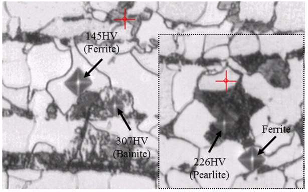
In addition, the hardness values of the alloys were measured to identify the microstructural constituents of the steel, and thus, determine whether the bainite transformation occurred, as illustrated in Fig 6. According to the literature, the hardness values of ferrite and pearlite ranged from 140 to 250 HV and that of bainite ranged from 250 to 310 HV when the carbon content of the alloy ranged from 0.12 to 0.16% [28]. The hardness values of ferrite, pearlite and bainite in this study were measured to be 145, 226, and 307 HV, respectively, which were consistent with the results reported in the literature. The hardness measurements along with the microstructure observations confirmed that bainite transformation occurred in the banded ferrite/pearlite structure, and that intermittent bainite packets had replaced lamellar pearlite structures.
Finally, the effect of molybdenum addition was also confirmed using HIC images captured with an ultrasonic scanner, as illustrated in Fig 7. The bright spots indicate HICs. The average number of HICs were 28 and 29 for the MF (Ni+Cu) and MA (Mo) steels, respectively. This implied that the number of HIC initiation sites for both steels were almost the same. However, the size (CLR and CTR indices) of HIC decreased significantly when molybdenum was added to the steel. In other words, in the MA (Mo) steel, small HICs were generated. This suggests that the molybdenum addition was not effective on HIC initiation, since the number of HICs was similar, but it was effective at inhibiting HIC propagation, since the HIC size was small.
Molybdenum in the normalizing heat treatment steels suppressed HIC propagation mainly by bainite transformation in the ferrite/pearlite banded structure. When reducing the total HIC index (CLR, CTR, etc.), the main concerns are controlling HIC initiation and subsequent HIC propagation. The mechanism of HIC propagation is believed to be closely related to the weakness of the microstructural constituents generated in normalized pressure vessel steels (banding, pearlite vs. bainite, etc.) [1,6-15]. The microstructural modification that resulted from the addition of small amounts of molybdenum to these steels also improved their resistance to HIC propagation. This was attributed to the morphology of the bainite, which was more random than the lamellar pearlite.
In a traditional normalized pressure vessel steel with a polygonal ferrite/pearlite banded microstructure, HIC propagation encounters little resistance [6,7,9-12,22]. The formation of polygonal ferrite and pearlite during the processing of the alloy creates localized areas of high stress concentration at the polygonal ferrite/pearlite interface, owing to expansion/contraction of various structures during the transformation. This generates potential hydrogen-trapping sites and causes subsequent HIC and crack propagation.
However, when the microstructure of the steel is modified by adding a small amount of molybdenum, replacing the lamellar pearlite with bainite packets intermittently placed along the banded structure, HIC can be prevented from further growth by reducing the overall CLR, as demonstrated in this study. Consequently, the addition of molybdenum effectively improved the resistance of the alloy to hydrogen-induced crack propagation by the intermittent replacement of lamellar pearlite structures with random bainite structures.
4. CONCLUSIONS
In this study, the effect of molybdenum addition on HIC in normalized pressure vessel steels was investigated. The addition of 0.1% molybdenum to normalized pressure vessel steels was found to modify the microstructure of steels, from polygonal ferrite/pearlite to polygonal ferrite/pearlite/bainite. The partial replacement of the lamellar pearlite structures with random bainitic structures resulted in two key structural characteristics which improved the resistance of these steels to HIC. First, improved contraction/expansion compatibility during the transformation and breaking-up of the banded microstructures was achieved. These effects reduced the overall residual stress intensity in the steel matrices. Reducing the overall residual stress state also reduces the localized stress concentrations, thus minimizing the number of potential hydrogen-trapping sites. Second, resistance to HIC propagation was improved by the random nature of the bainitic microstructure, which blocked the crack path and changed the direction of crack propagation. Because of these two key features, the average CLR and CTR performances of normalized pressure vessel steels for sour service applications were improved.